
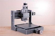
After reading a bunch of positive reviews, I purchased a Zen Toolworks 7×7 CNC machine on eBay. It came with three SST43D2121 stepper motors, a 3-axis Univelop TB6560v2 motor controller , and a spindle (high speed 36v milling motor). There is a remarkable absence of documentation for this stuff on the internet…hopefully this blog post will help.
I purchased a a MeanWell model S-100F-12 12v power supply ($20 on eBay) that supplies 12V/8.5A and connected it to the +7, +12v, GND inputs on the motor controller; numerous posts indicated that the 7v input can take 12v and so far I’ve had no problems with that.
The wiring to the stepper motors is just as described on ZTW’s website:
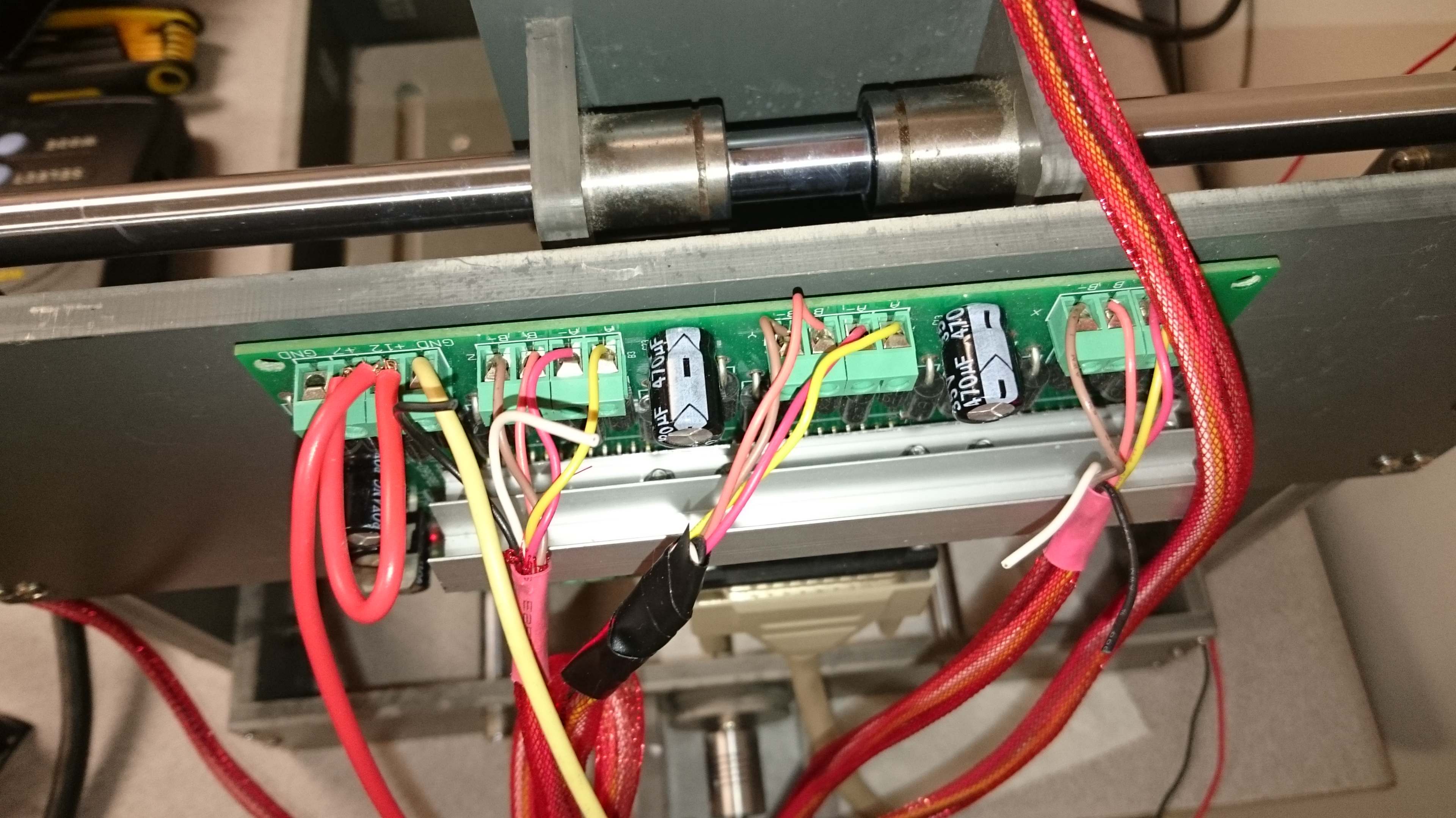
Stepper motor wiring
The motor controller has two sets of DIP switches for each motor: one has 2 switches and the other has 4 switches. On the 2x switches I set 1,2=ON. On the 4x switches I set 1=ON and 2,3,4=OFF.
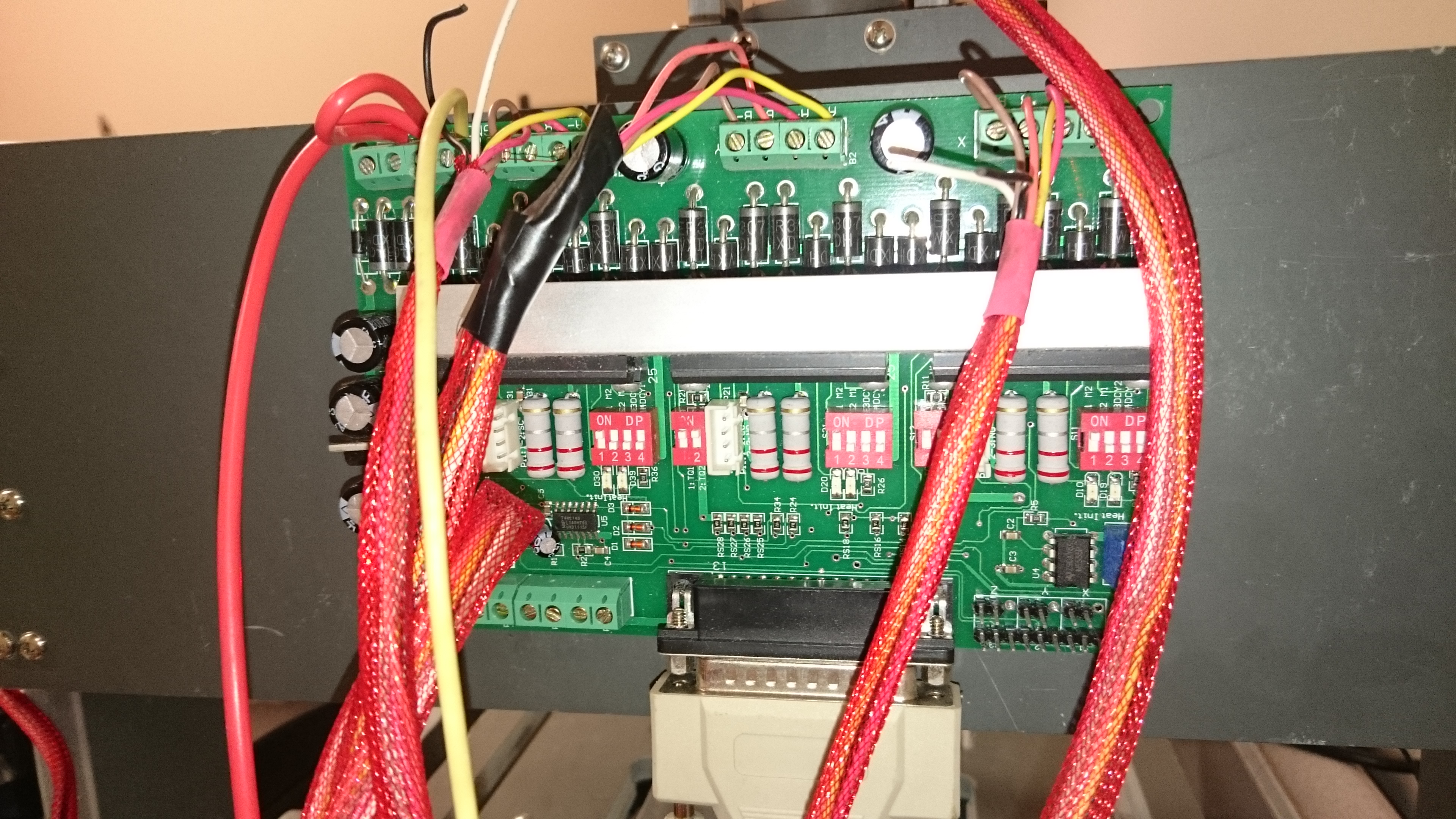
DIP Switches
This configures the motors for minimum (20%) current and smoothest movement (1/16 microsteps, 0% decay). This was determined by trial and error. Using the lowest load setting was important because the software I’m using (LinuxCNC) turns the motors on when powered; they are either held locked in place or driven (moving) but never turned off; so they are constantly drawing power…with 20% current, they stay cool and the 12v supply is never drawing more than 9.x Watts for all 3 motors and the controller. Using the 1/16 microsteps made a huge difference in smoothness of movement; otherwise moving the motors was very noisy.
The motor controller connects to the computer using a straight-through DB-25 cable. The pins are used as follows:
2 = Out = Step X
3 = Out = Dir X
4 = Out = Step Y
5 = Out = Dir Y
6 = Out = Step Z
7 = Out = Dir Z
8 = Out = Enable Y
9 = Out = Enable Z
14 = Out = Enable X
10 = In = Emergency Stop (low***)
11 = In = Limit X (low***)
12 = In = Limit Y (low***)
13 = In = Limit Z (low***)
1,15,16,17 = N/A = Not Utilized
18-25 = GND
***Signals are Active Low
Note that the Enable line must be active (high) for a motor to turn. When properly configured, the software will enable the motor when the machine is powered and disable the motor when the emergency stop button is pressed (in software or hardware) which powers-down the motors.
I’m using LinuxCNC for the control software; it’s free and I like linux. You can read about it here. The software is extremely configurable which makes figuring the setup out problematic. The software comes with two configuration wizards; one is for stepper-motor-based machines. I used this and created a configuration file named ztw7x7, but the wizard doesn’t allow you to configure the Enable pins properly. In the end, I had to edit the .hal file by hand to add definitions for Xenable, Yenable, and Zenable. This link was very helpful. I’ll post the edited file shortly.
There are many good choices for controlling NEMA17 stepper motors (1.2A/phase) including Arduino (Uno or Mega2560) with GRBL software (optimized for Mega2560 here) with a CNC shield using the Allegro A4988 or TI DRV8255 drivers (1-2A w/fan) or TB6600 stepper motor drivers (3.5A). See install info here. Note that the drivers must be adjusted for max current and many suggest adding over-voltage protection for them including a 100uF cap across the motor. I would consider a suitably sized TVS diode instead because most 100uF caps aren’t rated for the ripple current they would experience.
Replacement spindles are available with 775 motors and the same ER11 spindle.