
Update 2023-July: I no longer recommend using this until ST software support improves. At present, there are simply too many issues and it is a frustrating experience. The software seems somewhere between alpha and beta quality: the software that does work has major issues and many important software applications (including from ST) don’t work with it at all (including openocd which works fine with other STLink V3s).
I do a lot of design and development work using STM32 microcontrollers. The low-cost STLinkV2 hardware debug tool is part of what has made these processors so successful: the ability to quickly, inexpensively, and easily flash and debug firmware is a big deal. ST has gone a long way to make life easy for developers and we love them for it!
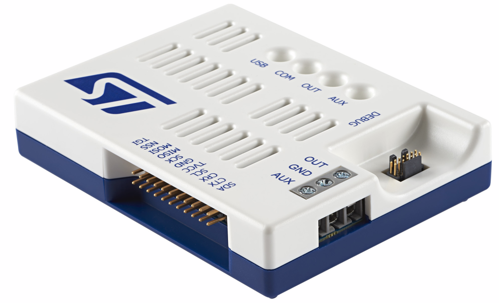
I have boxes of STLink V2s and clones; I use them all the time. Recently, I’ve started migrating to the STLink V3 and this post covers their most expensive variant: the STLINK V3-PWR which integrates some interesting features including:
- SWD debug tool (flashing, debugging target)
- USB-to-serial converter
- variable power source for target (1v6 to 3v6 in 100mV steps)
- dynamic current monitoring (100nA to 500mA) with 100ksps (50kHz BW)
It has additional hardware capabilities (SPI, I2C, GPIO, JTAG) that I haven’t tried yet (and it’s not clear that software support for them is ready).
Key Strengths
- The STLink v3 is fast for flash/debug – even faster than the V2 (which was plenty fast)
- The integrated serial interface works perfectly and saves another plug
- Nice injection molded enclosure
- The variable power source lets me test devices at voltages other than 3v3 and 5v which is more useful than it sounds…it’s often important to understand how the DUT will operate at 1v8.
- The ability to monitor dynamic power consumption during development is incredibly useful. I didn’t fully understand this until I started using a Joulescope and realized how much added visibility it provided. I now routinely develop with the DUT powered through a Joulescope so I can better “see” what’s happening. The V3-PWR dynamically switches between 4 current ranges to provide a huge dynamic measurement range without imposing excessive burden voltage.
Cost:
- $95 is crazy expensive for an STLink and serial dongle (V2 clones and serial dongles are individually available for as little as $2 from AliExpress in nice compact aluminum shells).
- $95 is crazy cheap for a dynamic power monitor that covers a wide enough current range for IoT development is hard to come by for even a fraction of the price. The Joulescope, is roughly 10x the price (but much more powerful).
- If ST make the design public as they did with the V2, we can expect to see the price decline dramatically once Chinese clones appear.
Hardware Limitations:
- 100ksps (50kHz claimed BW) sounds great, but in reality, that sample rate doesn’t provide enough resolution to understand the dynamic power consumption of many IoT devices. It’s super-common for battery-powered devices to wake briefly (uSeconds), do something, and go back to sleep. This is one of the major differences with the Joulescope (2Msps, 300kHz BW).
- No pass-through current/power monitoring. Batteries have higher impedance than most line-powered supplies and that impedance varies with temperature and other dynamic feactors (e.g. passivation). The V3-PWR lets you observe the consumption of the DUT, but not its dynamic interaction with a battery. (another difference with the Joulescope).
- Power to the DUT is via ~3.5mm screw terminals…not banana jacks, not pluggable screw terminals, not even lever terminals…this was the wrong place to save a few cents.
- Connection to the computer *requires* USB-C or the rare USB-A port that supports both data and charging. Maybe this isn’t a big deal or even a limitation, but it’s worth being aware of.
That Dang STC14 connector
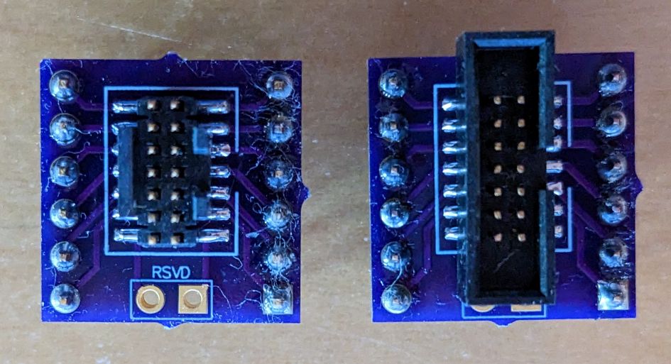
- The biggest DOH! with the entire STLinkV3 series is ST’s adoption of a 50-mil “STDC14″ connector. 0.050” (1.27mm) connectors are simply awful, particularly for developers. Many targets won’t have the same STDC14 connector and now you can’t use the ubiquitous 100-mil dupont jumpers as we did with STLinkV2. Instead, you need a breakout board to adapt the 0.050 pins to 0.100. You can get inexpensive STDC14 breakout boards from OSHPark (9 PCBs for $11.10 shipped) and mount either these nice but very expensive and somewhat fragile Samtec connectors (left) or these much cheaper and more rugged CNC Tech connectors (right).
Software Limitations
- No cumulative or average power measurement. This is a huge deal for battery-powered devices (and one that ST can and should add to their software). Understanding average power consumption is key for most battery-powered IoT devices. The sampling limitation might limit accuracy, but this is an easy-to-implement and important missing feature.
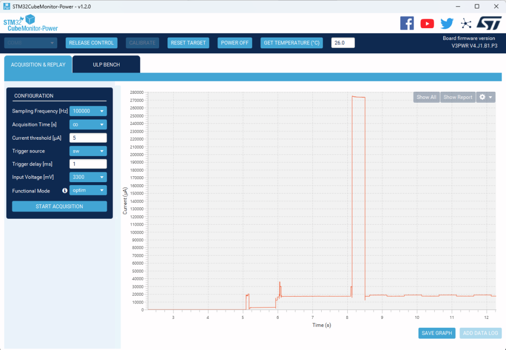
- The UI is limited (something ST will also hopefully improve over time). It provides a graphical display of current measurement (see below), but is missing features we’ve come to expect from scope-type equipment such as: horizontal or vertical cursors to make and document precise measurements, automatic axis scaling, adjusting the time-base dynamically, etc. ST software developers would be smart to license Joulescope software for the V3-PWR.
When the software associated with the V3-PWR matures, it will get a thumbs up from me. If/when cheaper clones start appearing, I’ll probably have a box of these to replace my STLink V2s. If ST provides an API, these could also form a very useful building block in many factory test fixtures.
Competitors
- Nordic Power Profiler Kit 2 (PPK2) – similar price, wider voltage/current ranges, can measure external current sources (i.e. battery), but no debug/serial functions and no enclosure.
- NXP MCU Link Pro – half the cost, but you must select one of two current measurement ranges using a jumper and neither of those ranges fully cover my measurement needs. Within the selected range, the MCULink dynamically switches between 2 sub-ranges, allowing good dynamic range, but not on the level of the other devices. It also has more limited power supply capabilities (two fixed voltages: 1v8, 3v3) and has no enclosure.
Disk Abuse
I left the monitor running overnight at a high sample rate with acquisition time set to infinite. It turns out that this writes a ton of data to the disk and by morning it had chewed through 160GB of disk space! Even worse, it’s not obvious where the disk space went! So for other users who find this issue, the power acquisition log files are in Users/myUserName/AppData/Local/Temp/Power_Monitor/Acquisition.
ST could significantly improve the software application (STM32CubeMonitor-Power) by adding a few features, some of which seem quite easy:
- Checkbox to En/Disable logging (off by default) so you can watch power consumption as you develop/test.
- Link to the acquisition logs folder so users can find it easily
- Stop/play button so you can pause acquisition to measure an event and then resume
- Cumulative power usage counter (so you can confirm expected average power consumption over a long test)
- Cursors (current and time) so you can measure and document events
- Auto-scale of the Y-axis should adjust to mA when appropriate. A scale from 0..500000uA is just silly and it’s surprisingly annoying to try to distinguish 15000 from 150000.