Sometimes you need a battery-powered oscilloscope. You may need it for use in the field where there is no AC power. You may need to take some measurements where you are 100% confident the scope is isolated from AC/mains (and there is no better guarantee of that than no connection to AC Mains whatsoever). You may simply need to give a demonstration of something where no AC outlet is convenient. Whatever.
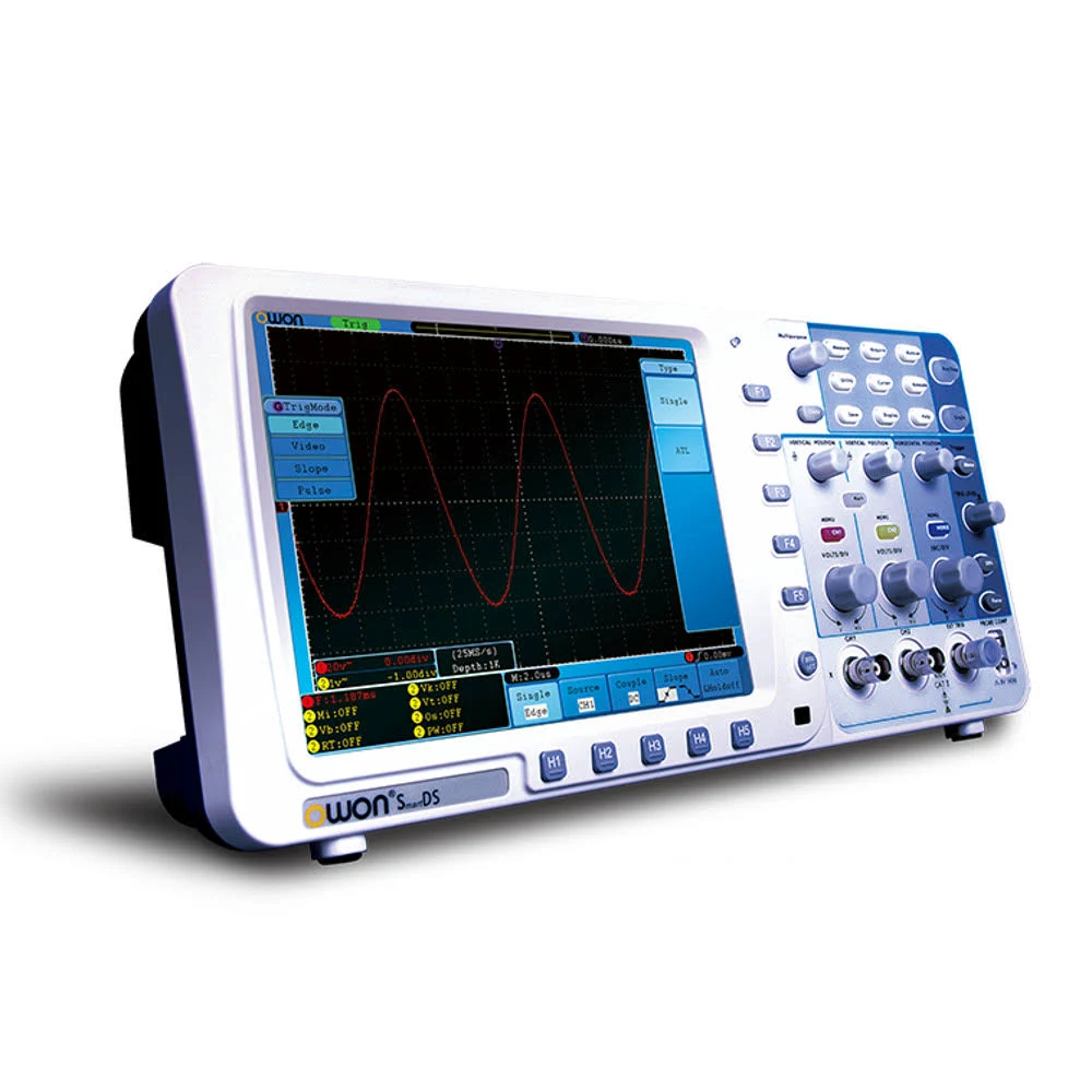
I’ve owned many handheld battery-powered scopes, but most aren’t nearly as good as a standard bench scope; the controls are harder to use, the display is too small, the specs aren’t as good. Fortunately, Owon, one of the Chinese brands I have found to be reliable over the years, makes their SDS Series of bench scopes that take an internal lithium battery. They are very thin, light, and come in 100MHz-300MHz bandwidths.
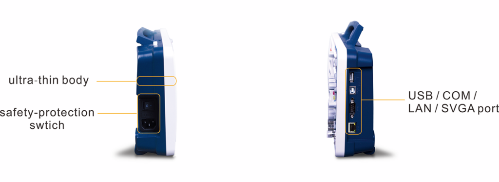
This is an old scope…at least 15 years old. When they first came out, they were very full-featured. Mine has a VGA video output (which makes it great for talks and demos), USB, and Ethernet jacks, and all of the features you’d expect in a DSO of its time. The fan is quiet too. You can read a critical eevblog review here which includes the obligatory EEVBlog teardown and describes many firmware issues that were later fixed. This guy did an insanely detailed teardown (really hacking) of the scope here. I have had mine for years and find it reliable and of good quality.
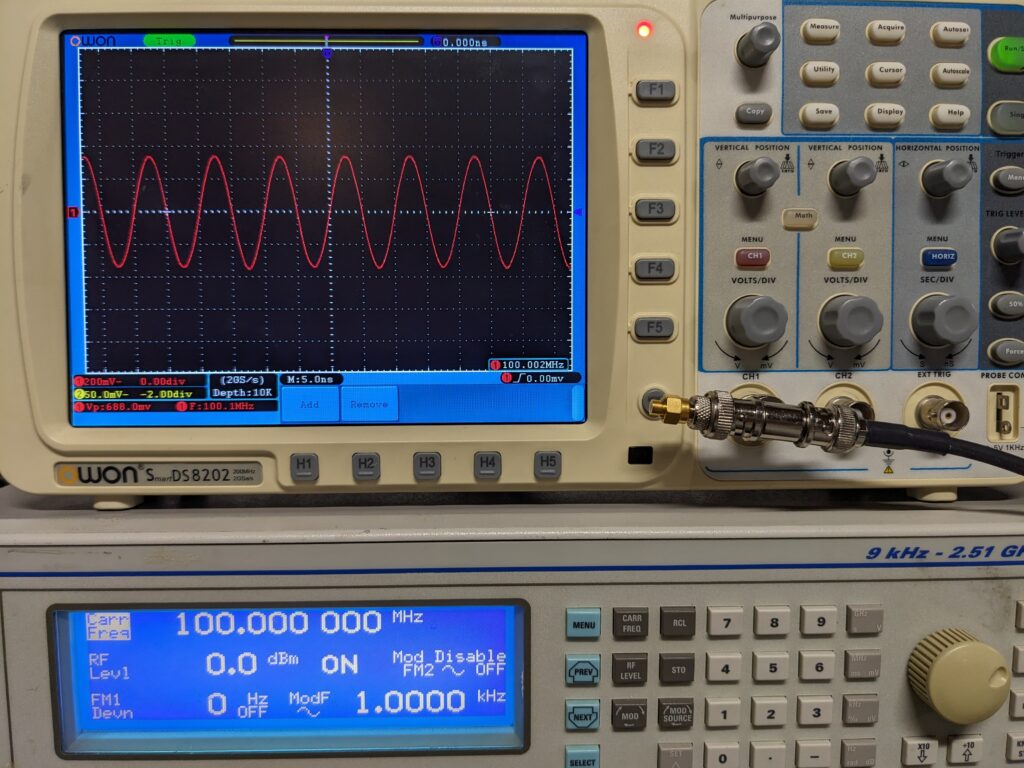
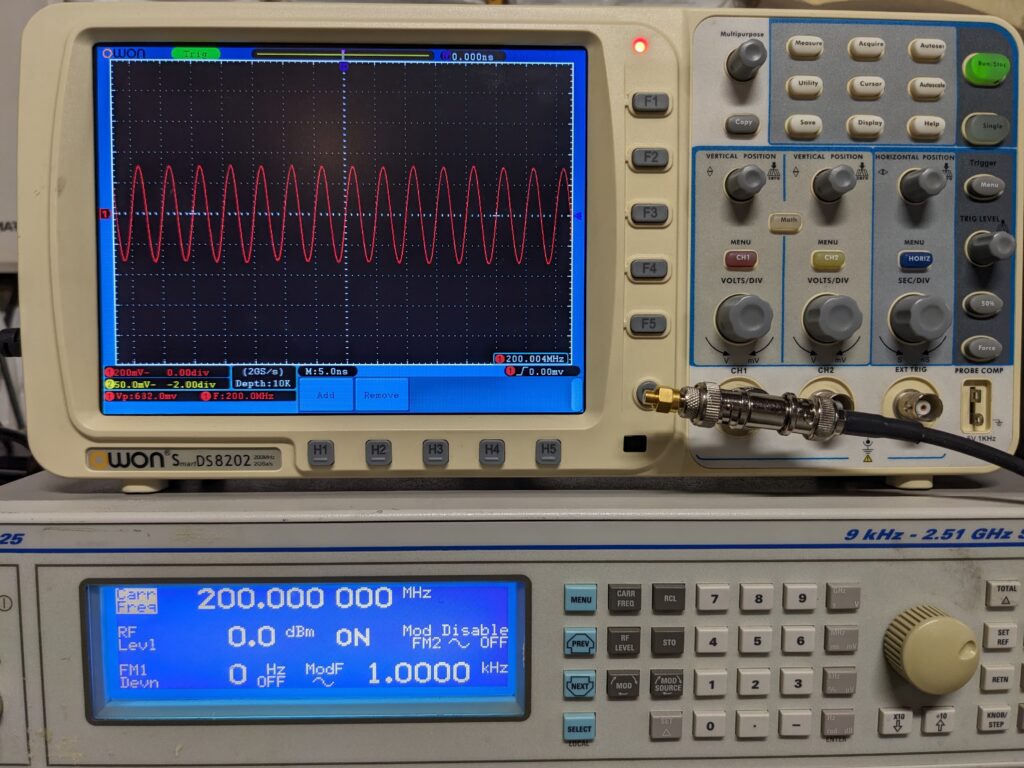
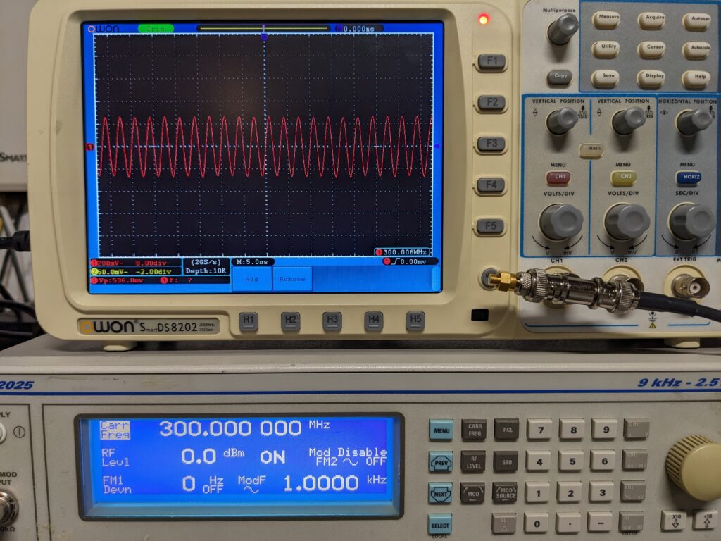
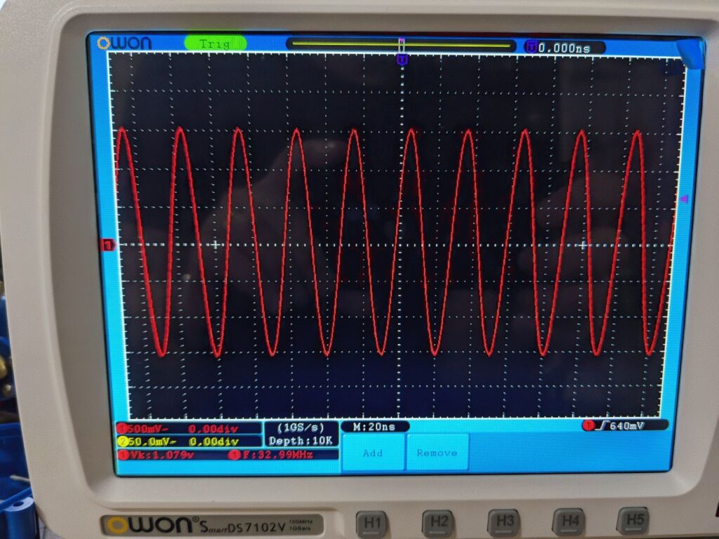
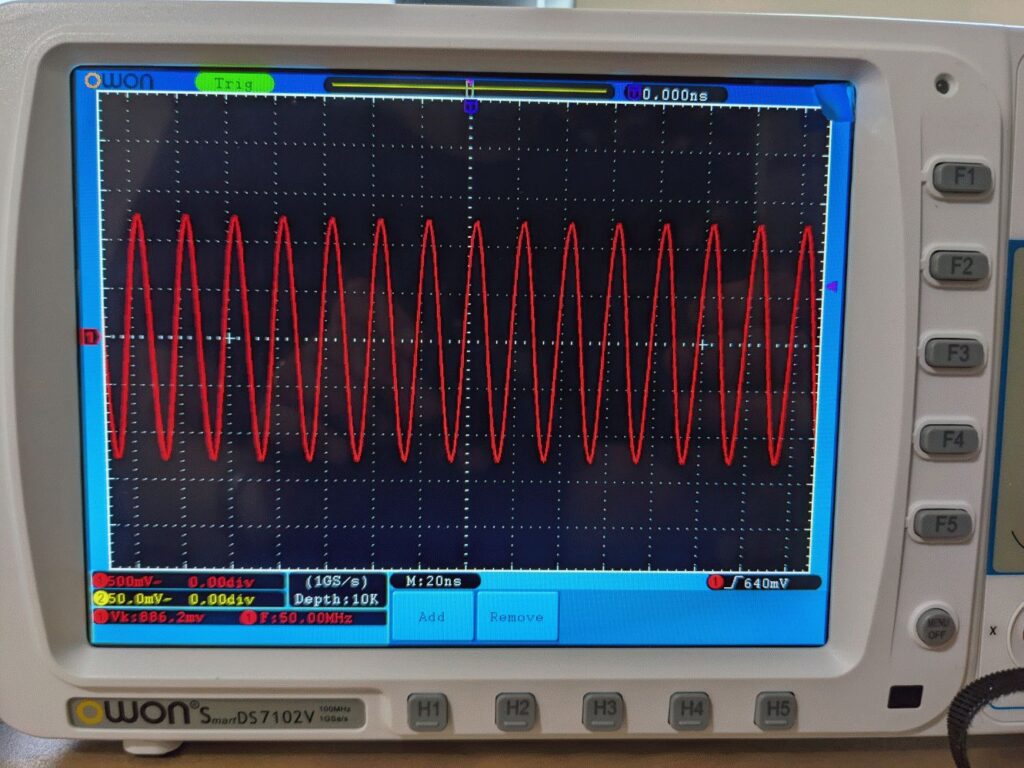
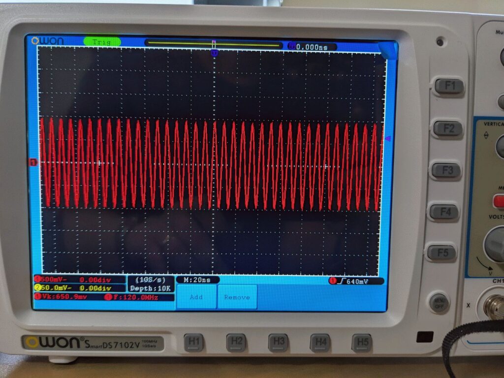
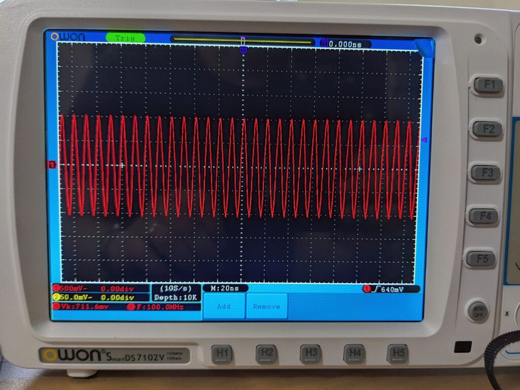
The scope meets its specs; I’ve had 100MHz and 200MHz versions and they both are true to spec. It samples at 10x rate (e.g. 100MHz samples at 1GS/s) and has a deep memory (10Mpts). The analog front end is a little noisy, but the trigger works well, the controls are very user friendly, and it just does what a DSO should do. Now what it doesn’t do, that matters to me, is decoding of digital signals (I2C, Asynch serial, etc.) and that’s the primary reason it is not a daily driver for me anymore.
The Battery
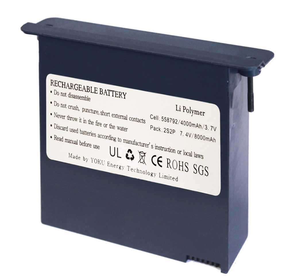
The stock battery option is a lithium polymer battery that often fails over time. Replacements are either expensive or unobtainium. You can find them on eBay for around $65 (often with high shipping). Fortunately, there are enterprising Chinese suppliers who have come up with a higher-capacity, low cost solution: a board that holds 4x 18650 or 21700 batteries and offers better protection/balancing and fits in the battery compartment: the EDSPack. It is widely available on AliExpress and eBay, sometimes for under $20 (without batteries). Their github site (see the EDSPack link) includes a downloadable STL for a 3D-printable holder – that I printed it in ASA and it came out *very* nicely. It fits the battery board and the scope perfectly. You will need 4x M3x6 bolts and 4x M3 nuts to secure the board into the printed holder.
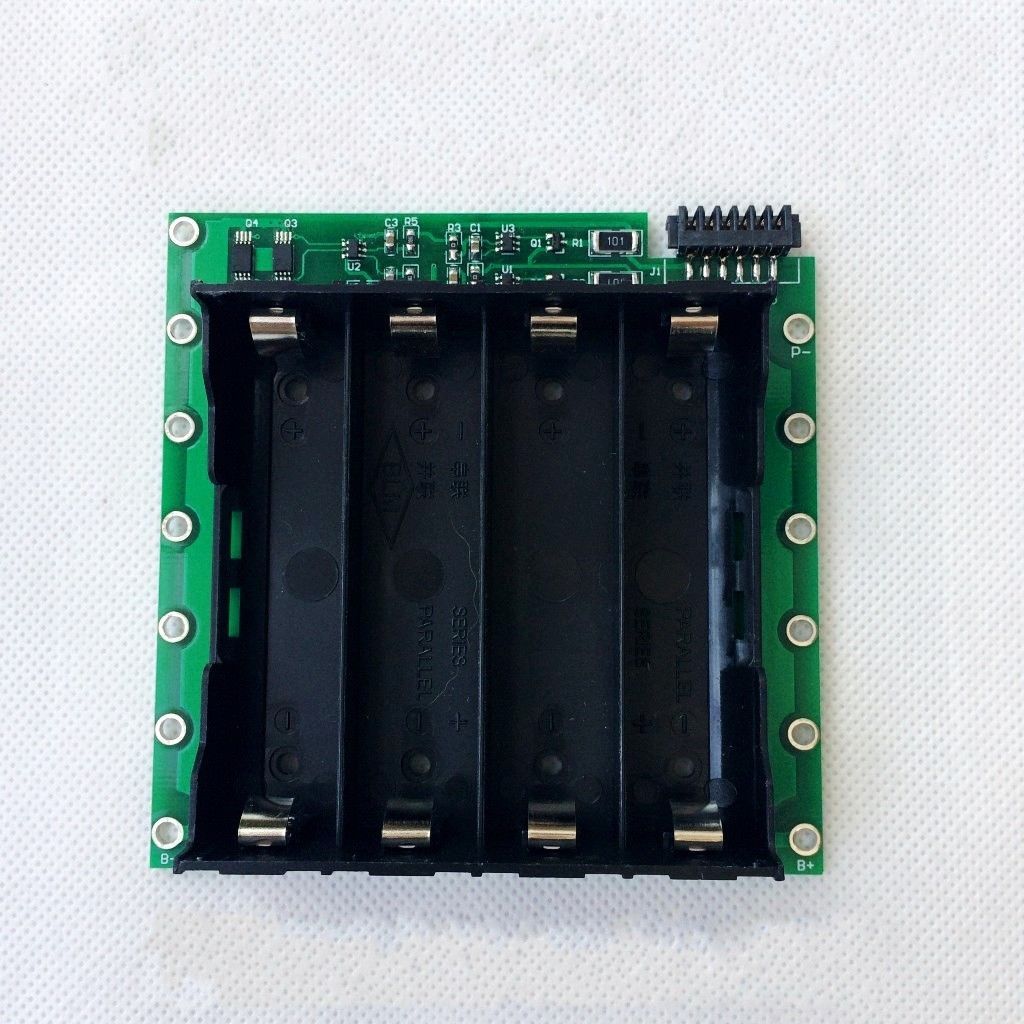

I prefer this to the sealed lithium polymer battery pack for several reasons, including that when the batteries die, you can just replace them. The board otherwise charges the batteries as with the OEM pack when it’s plugged into AC power.
NOTE: if the scope is not plugged in, it places a significant drain on the batteries (~2.3mA) even when it is off. This means that if you don’t use the scope for a while and it is not plugged in, you will need to plug it in and charge the batteries before you can use it on battery power.
The scope also has an available carry bag that’s pretty cheap on AliExpress.