There are three things every STM32 developer wants from a debug dongle:
- Power (3v3, 1v8)
- SWD
- UART
So I was excited when ST released their next gen debug interfaces (STLinkV3) and had included support for 1v8 targets and a UART. Was third time a charm? Unfortunately, not. Although the UART and support for lower-voltage targets is a welcome addition, ST made three unfortunate moves with the MINIE that are hard to fathom:
- Most notable was their attempt to force use of the STDC14 connector by *only* providing a 0.050 pin header for connections to the target via a fairly fragile connector. It would have been *much* better for it to have a shrouded 2×5 0.100″ pin header (like the “aluminum shell” STLinkV2 clones show below). These would allow use with the ubiquitous Dupont jumper wires that litter every developer’s desk. A tiny PCB with an SMT 2×5 female 0.100 on one side and STDC14 male on the other could have easily adapted to STDC14 when desired, but it’s much harder to go the other direction.
- It can’t power the target. Even the sub $3 STLinkV2 clones can power targets at 3v3 and 5v. This is incredibly useful, adds virtually no cost (5V is available from the USB i/f and there’s already a regulator on the STLink for its own uC). An STLink that has SWD, UART, and Power is exactly what every STM32 developer wants…now you need the MINIE and an external power supply!
- Finally, there’s the USB-C female connector. Even new laptops have very few USB-C ports (but many USB-A ports); the desktop situation is even worse. The interface itself is only USB 2.0 and the board and can’t supply power to the target, so I can see no rational reason for this choice. I suspect some PLM who has never done any development decided this would be “forward looking”.
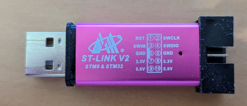
The sub-$3 “aluminum shell” STLinkV2 clones nail the mechanical design. They can also power 3v3 and 5V targets. It’s only missing a UART and 1v8 support to be perfect.
So what to do?
You can keep using STLInkV2s, but as designs increasingly move to 1v8, that becomes a problem, requiring a high-speed voltage converter…The STLinkV2 runs an STM32F103 which only runs to 2v0 so you can’t just replace the regulator…and the STLink V2 lacks a UART.
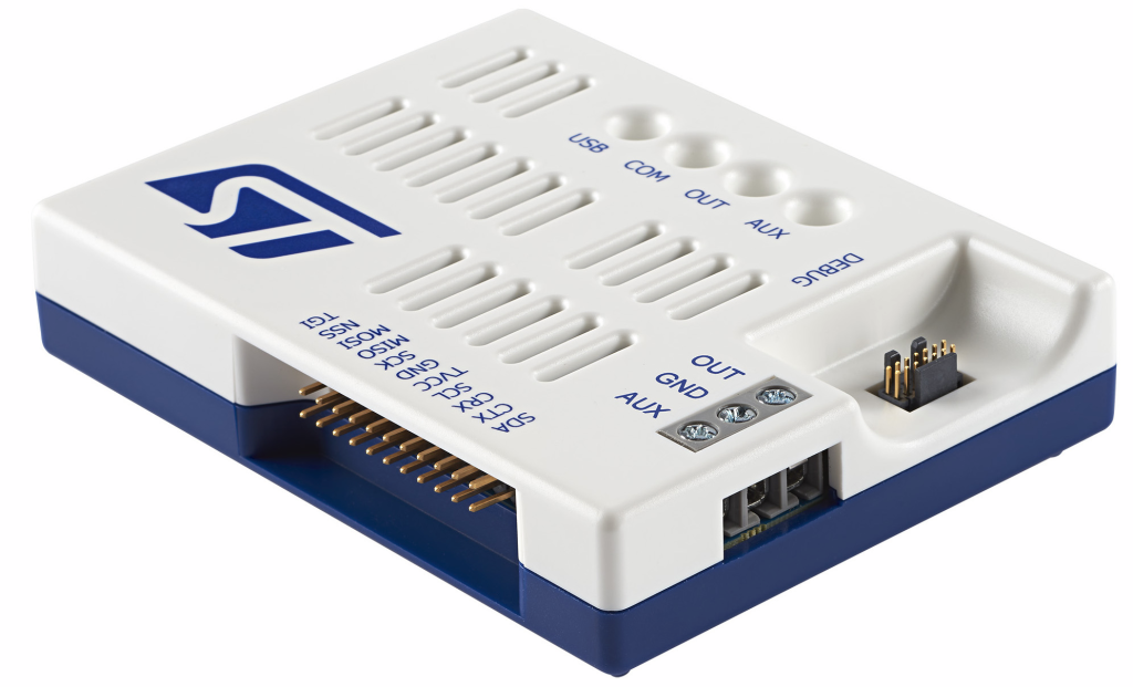
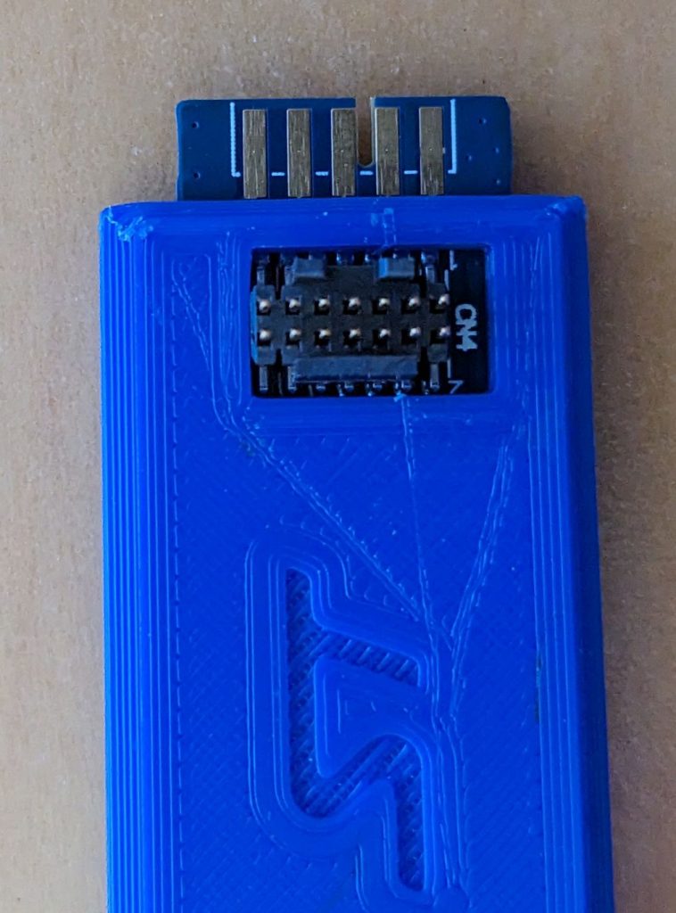
There are adapter boards to convert STLink V3 STC-14 connector to 0.100 pin headers; I covered these in an earlier post discussing the STLink V3-PWR (which does supply power and is a single device solution for most STM32 development/debugging). However, the adapter boards just add another set of wires to clutter your bench and come loose at inopportune times. Fortunately, ST provided an edge connector on the V3MINIE for an imagined board-to-board configuration, and although they spaced the pads at 2mm, you can make them work for a 2.54mm pin header.
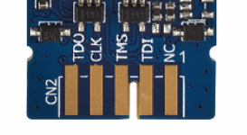
The JTAG/SWD pins map to SWD as:
- TMS = SWDIO
- CLK= SWCLK
- TDO = SWO (which I rarely use)
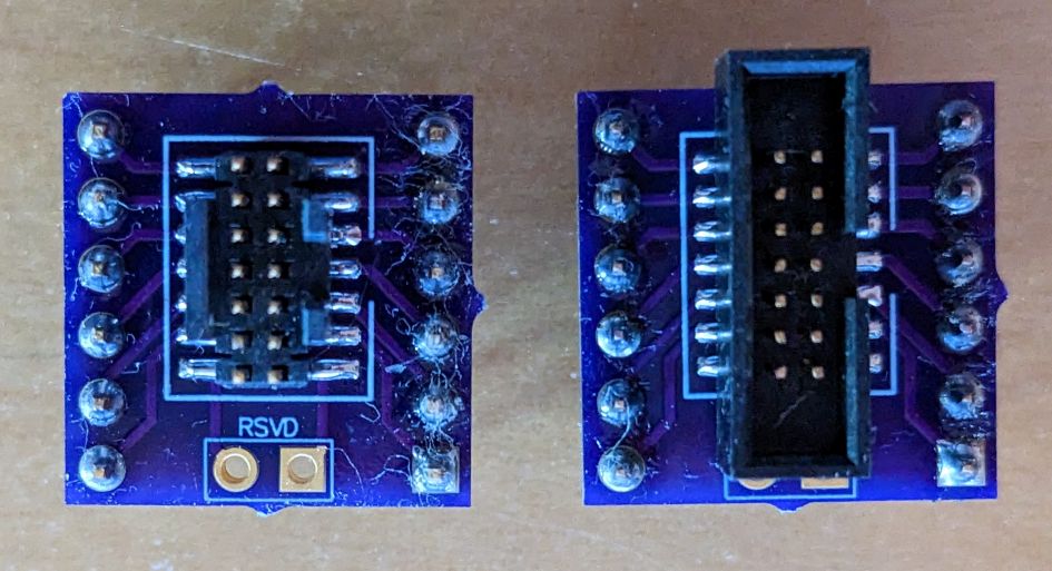
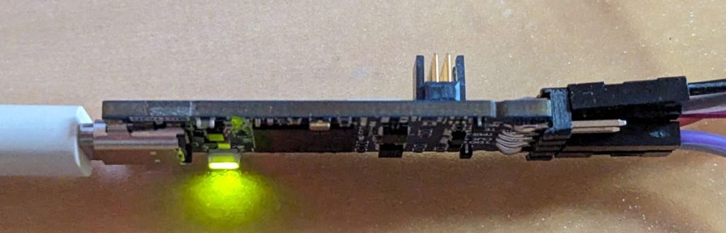
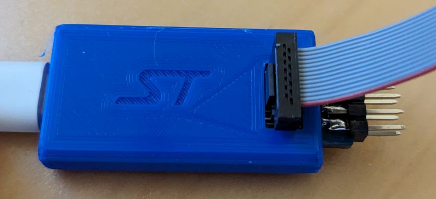
It’s easy to solder a 2×5 0.100″ (2.54mm) pin header onto the 2mm pads; just center the middle pin on the middle pad and the other pins are close enough that you can easily make it work.
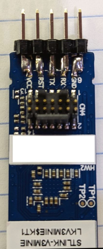
The soldering here is sloppy, but it shows the concept. The 2×5 pin-header is rock solid when mounted and provides access to all of the pins I use. The UART-side pins (shown to the left) are obvious.
Next time I’ll use a shrouded connector, to prevent accidental contacts and also to have a place to put a small label for each pin (you can’t see the silkscreen for the edge connector contacts when the board is in the 3D-printed enclosure)
ST has also kindly placed an STL file for a 3D-printable case on the product page (under CAD Resources). If you’re using Cura to slice the model, you’ll also need to uncheck the “Union Overlapping Volumes” box in the Mesh Fixes section of the print settings or it will fill in the STDC14 opening. Otherwise, it’s a very nice, compact enclosure with an excellent snap-fit and it holds the PCBA securely.
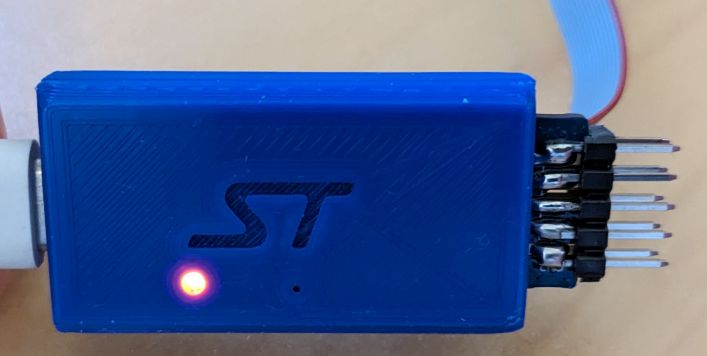
The original version of the enclosure posted on ST’s product page had the opening for the STDC14 connector slightly shifted and so you had to cut it a bit to make room for the connector. Within a day or so of reporting this to ST (8/2/2023) they had fixed the issue and sent a new STL file to test and it fit perfectly. I expect it will replace the original version shortly.
Go ST!
Next up:
Figure out how to get the SWD functionality working from the 0.100 header pins- Find a solution for powering the target. If you know of any, please let me know!
ST: if you’re listening, PLEASE give us a nice compact dongle like the V3MINIE but with a USB-A connector, pads for 0.100 pin headers, and 3v3 and 1v8 power outputs.
Update 5/1/2025
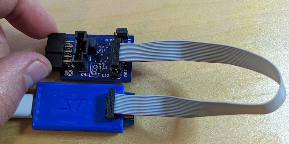
Because both the 0.050″ STDC14 connector and 0.100″ flying leads are a pain, I spun a quick 2-layer adapter PCB with a 0.050″ connector (CNC Tech 3221-14-0100-00) that connects via ribbon cable to the MINIE and a more robust 5×2 pin 0.100″ connector (Sullins SFH11-PBPC-D05-RA-BK) that plugs directly to my STM32 target. The SWD connections (DIO and CLK) can be disconnected via jumper so the UART alone can be used.
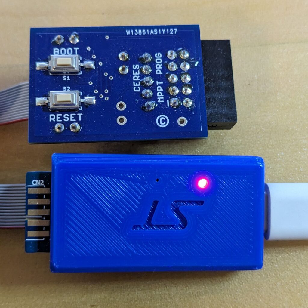
On the bottom of the board, tactile switches make it easy to manually reset the target and/or to put it in the DFU bootloader mode.
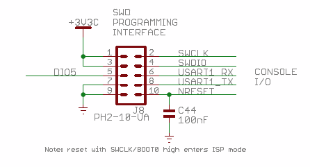
The target connector is a super-cheap 2×5 keyed 0.100″, shrouded pin header that brings out all of the signals needed for factory programming and calibration as well as development and debugging.
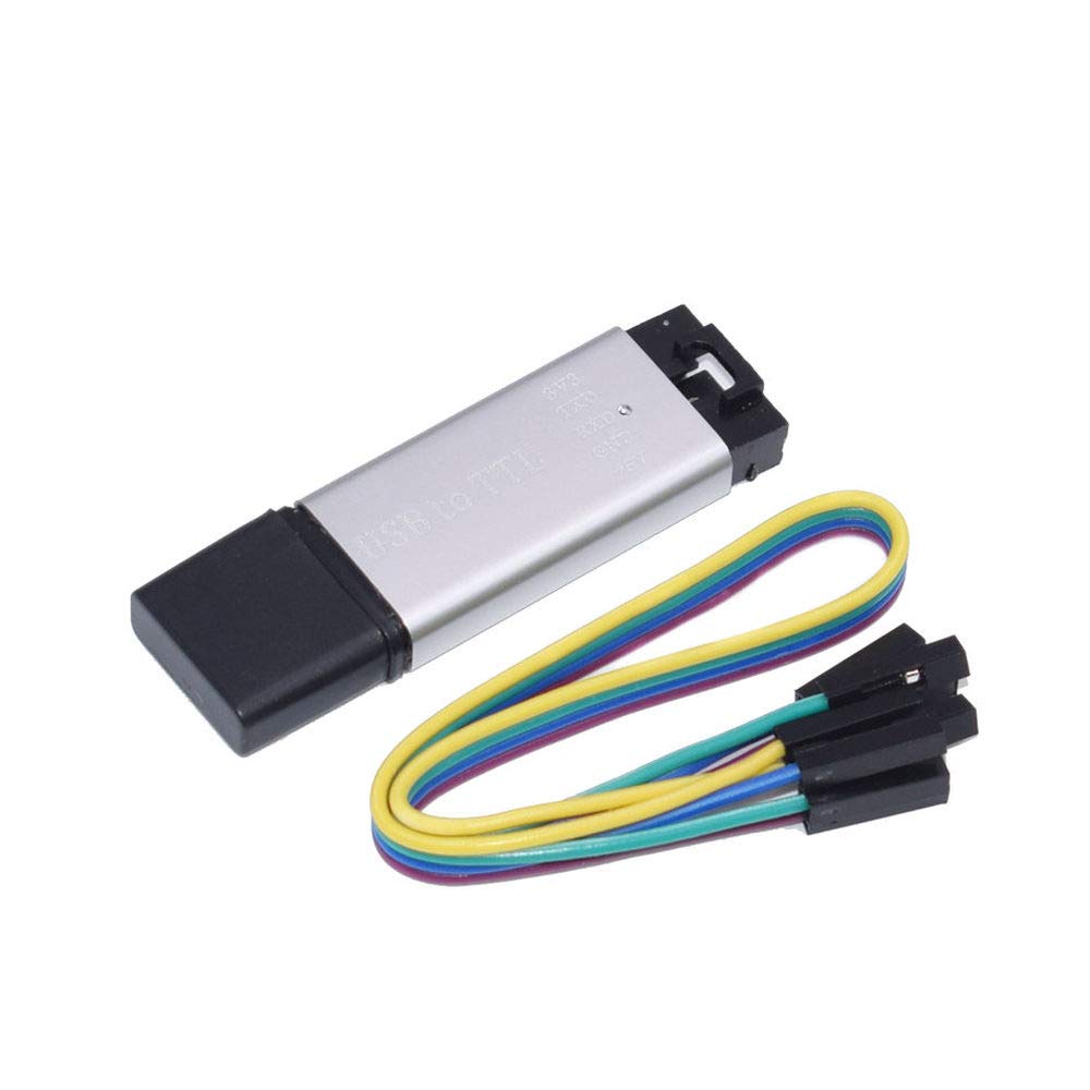
The adapter board also has a 1×5 locking header (Molex 0705430004) to support a straight-through, locking cable (Molex 216270-1053) to allow use with the ubiquitous low-cost “aluminum shell” USB-to-TTL UART dongles. Those can then be used in place of the MINIE if only serial comms with the target are needed. These adapters can supply power as well which is often handy during development or debugging. When used with these dongles, the adapter includes a jumper to disconnect power or to allow measuring target power consumption.