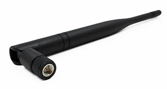
I do a lot of work in the sub-GHz ISM band and there are a lot of antenna vendors whose quality varies broadly. Consider the case of two antennae: The first was purchased from AliExpress vendor CS Family. These were sold as 915MHz antennae with 3dBi gain (this).
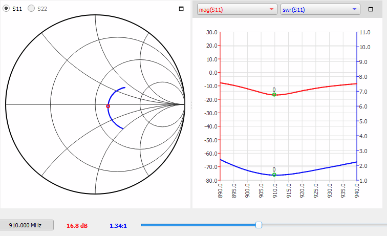
It’s centered at 910MHz and its best-case SWR is 1.34:1. At the band edges, it offers 1.57:1 at 902MHz and 1.77:1 at 928MHz. This is acceptable; I consider anything better than 2:1 acceptable for a cheap antenna and this meets its spec across the band. The impedance is 75 -j47. It’s not pretty, but it will do the job.
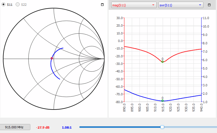
However, compare it to one of my favorite compact antennae from TE/Linx: the ANT-916-CW-HWR-RPS (datasheet) claims 1.2dBi and better than 2:1 VSWR.
This antenna is nicely centered in the band and offers an amazing 1:08 SWR at 915MHz, 1.57:1 at 902MHz and 1.40:1 at 928MHz. Impedance is 46.59 +j0.70. Now that’s pretty!
In fairness, both antennae meet their spec (better than 2:1) and the AliExpress antenna cost only $2.16 whereas the Linx antenna cost $13.50…so I cut the AliExpress guys some slack 🙂
Measurements taken using a NanoVNA SAA-2N with VNA Qt software. I might break out a nicer VNA some time and repeat these tests, but for quick measurements, I’ve found the NanoVNA2 to be remarkably accurate; it’s insane what $110 can buy these days. Note: if you have a NanoVNA2 SAA-2N, the firmware, manual, schematic, and a version of VNA Qt that works with it can be found here. The 1.3.07 firmware (Aug 30, 2022) offers many important features and if you’re running older firmware, you probably want to update (instructions are in the manual). The only thing I couldn’t find a way to do using the LCD UI was port extension, but it’s easy with VNA Qt.
Cybersecurity (or lack thereof) is a disaster. Every website in the world is under constant attack by networks of automated hacking robots (bot nets) checking for weak security.
Everyone should use a password manager such as PasswordSafe or BitWarden . These tools will generate a different random password for each account/website you use and store it securely encrypted. You “open” your safe by entering a master password which then decrypts all the stored information. The tools will also let you securely store things like the URL of the website, and some free form information like account numbers. All you need to memorize is one master password (make it something good – an unusual phrase).
Because so many sites use bad security practices, there are now massive databases of hacked usernames and passwords available. This would have been impossible if companies followed best security practices of even 30 years ago. This means you are particularly vulnerable if you use only one or a few passwords for many sites. Even if your password is good, you re depending on the developers of the website you entered that password into for its security.
Using different randomly generated passwords for each website means that even if one site uses bad security practices and is hacked, ONLY your account at that site is compromised, not all of your accounts.
Developers: NIST has issued guidance on password practices that are quite good and everyone who writes software that requires password authentication should read this:
Some of the simple things you can (and must) do that have been common practice since at least the 1990s:
Don’t store passwords. Anywhere. Not plaintext or encrypted. You should only store a one-way hash of the salted password. Even ancient hashes like MD5 are much better than storing plaintext or encrypted passwords, but there’s really no excuse for using anything weaker than SHA256 or better these days.
Use password spinning: after every N failed attempts, add a small (1-3 second) delay. This effectively prevents brute-force/rainbow hacking.
Test new passwords against a database of known hacked passwords. (no “OpenSesame”)
Require reasonable minimum password lengths. (no “123”)
Not from the 90s, but probably a good idea these days:
If you have a fast and easy way to do 2FA (e.g. biometric), use it.
Some things you should NOT do (and that drive me crazy when I see it):
Require users change their passwords frequently – this is just nuts; it drives users crazy and incentivizes them to use simpler and easier to remember passwords.
Have special characters users must/can’t use in their passwords. This discourages the use of good random password generation and is even worse without it.
Disallow users from seeing the password as they type it (that should be an option)
Time-consuming 2FA methods (like text messages or validator apps) for things that don’t need that level of security. It introduces a super-annoying delay in accessing your data/app. Biometric 2FA is OK.
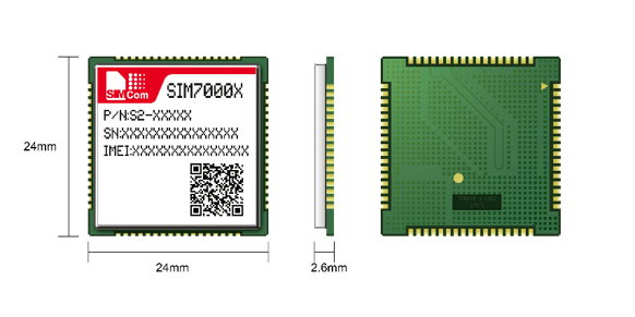
I designed the Simcom SIM7000x into a product some time ago; although it is a little dated, it still offers an extensive set of features for a remarkably low price. In particular, it combines a (2G, 3G, 4G/LTE) cellular modem with a GPS receiver and supports very low power modes of operation. The problem is the documentation and I’m publishing this post in the hope that it will save others some pain.
First: the grousing:
Like most communication modules, the SIM7000x is controlled via an asynch serial interface using the venerable AT command set dating back to POTS modems. That so many manufacturers still use this 1981 control interface is remarkable (and so awful that I will post about just this issue in the future). There are three particularly bad things about it:
It tries to combine human and M2M communication and, as a result, is terrible at both. For M2M, there is no framing, error checking, data typing, MIB, easy way to separate tokens, or standard error handling.
The data and control streams share the same serial interface so you can’t (easily) interact with the module while it is transferring data (yeah, I know about CMUX).
Because the interface is so old, has been used by many manufacturers, and several standards bodies have attempted to tame it (each differently), there are now gobs of similar commands that leave a confusing and inconsistent interface which is difficult to code to.
Some day, a smart manufacturer is going to fix this. The SIM7000x has a rich set of peripherals, gobs of I/O, memory, and processor power; it could easily deprecate the AT interface and add something sane. A modern interface would support I2C and/or SPI, layered communication protocol, and standard MIB interface. Nevertheless, the SIM7K modules offer a great deal of functionality, are FCC and PTCRB modular certified (so they’re ready to use on carrier networks), and can be purchased for a reasonable price.
My Applications
Nearly all of my design work involves embedded systems (there are often extensive backend server systems too). For the embedded systems, I typically want to establish a connection to a remote server and exchange data; usually using a RESTful or MQTT API in a format like JSON or msgpack. Because the devices are typically remote from the server, I need:
secure communication (TLS)
server authentication (public key certificates)
remote device authentication that can be revoked
The SIM7000x supports all of this, but the specifics are not always obvious or convenient despite the 281 page AT Command Manual and numerous application notes including TCP/IP, SSL, and HTTP(S) Simcom provides. The manuals should probably be much longer and take more time to explain the API architecture and how the commands. I’ll provide an overview below of how to do secure data communications and include discussion of some of the potential areas of misunderstanding. Note: the discussion below assumes you have the latest firmware installed on the module.
LTE Connectivity
In America, GPRS (2G) and EDGE (3G) data networks have been completely discontinued as of the end of 2022. Most low-cost data connectivity now relies on 4G/LTE which the SIM7000x supports. All the major cellular carriers (AT&T, Verizon, T-Mobile, etc.) support LTE and you can buy SIM cards for any carrier to use with the SIM7K modem module. I use the MVNO Velocity/Flolive; which offers multi-carrier SIMs so the device will connect to whatever carrier is available, anywhere in the world it is deployed (i.e. you’re not tied to one carrier’s network).
Let’s look at the AT commands involved in bringing up an LTE data connection:
Initial Startup of the Modem
If you are using the DTR wake/sleep functionality, set the DTR pin to wake the modem
Send the modem an AT command and wait for OK response to see if it is already awake
If the modem does not respond, try a hard reset wait for the RDY prompt
If the modem still does not respond, toggle PWRKEY and wait for the RDY prompt
Repeat the above a few times until you get a RDY or OK prompt
Reset the modem configuration so you’re starting from a known state using the command: ATZ (and wait for OK response)
Enable sleep mode if you want low power operation (which I usually do) with the command: AT+CSCLK=1 (and wait for OK response) (note: this is a persistent setting, you only need to do it once – noted as “AUTO_SAVE”)
Configure the modem for LTE operation only. There are many 2G, 3G, and 4G bands to be scanned; by limiting the scan to LTE bands, you can dramatically speed up the time it takes to initially find a carrier (the modem will remember after that). Send the command: AT+CNMP=38 (and wait for OK response) (AUTO_SAVE) (note: this is a persistent setting, you really only need to do it once)
Note: if you know which carrier(s) you will be using, you can further speed up the initial carrier discovery by restricting which LTE bands are scanned to only those supported by the carrier.
Configure for LTE-M1 only for the same reason (unless you need NBIoT) using the command AT+CMNB=1 (and wait for OK response) (AUTO_SAVE)
Disable the Network activity LED if you wish to save power using the command: AT+CNETLIGHT=0 (and wait for OK response) (AUTO_SAVE)
Gather and cache any data you want about the modem and SIM card using commands like: AT+GMM, AT+GMR, AT+GSN, AT+CIMI, AT+CCID
Register with the Carrier Network
Check if the modem has already registered on the carrier network using the command AT+COPS? (look for a response like +COPS: 0 which indicates that the modem is searching for a supported carrier or a response like +COPS: 0,0,”AT&T FloLive”,7 which indicates that the modem is connected via LTE.
If the modem is not connecting, you can forcibly cycle the modem through de-registering and re-registering with the carrier using the sequence: AT+COPS=2 and wait for OK then AT+COPS=0 and wait for OK.
When the modem connects to the carrier, it can send (depending on some other configuration settings) an asynchronous notice like: *PSUTTZ: 24/06/13,22:40:35″,”-16″,1
Once AT+COPS? indicates that you’re connected to the carrier, you can check things like the signal strength with the command AT+CSQ (and wait for the response like +CSQ:25,99 followed by OK)
Connect to the Packet Data Network
Your data provider may be the carrier like AT&T or a third party MVNO like FloLive that uses many carriers. You will need to know the APN for your data provider to get IP connectivity.
You can either hardcode an APN (like flolive.net) or, when using LTE, request the APN from the carrier using the command: AT+CGNAPN (and wait for a response like +CGNAPN: 1,”flolive.net”). Note that not all carriers will provide the (correct) APN so you may be better off hard coding it.
Set the APN using the command: AT+CSTT=”flolive.net” (and wait for OK) (not persistent)
Check to see if the modem has connected to the packet data network using the command: AT+CEREG? (the response that indicates you are connected +CEREG: 0,1 or +CEREG: 0,5 or are not yet connected +CEREG: 0,2 (searching/trying to attach).
Handle critical errors such as +CEREG: 0,0 (modem gave up searching for a carrier) or +CEREG: 0,3 (registration denied). Generally your options in these cases are limited to periodically de-registering from the carrier network and re-registering (as described above with AT+COPS=2 then AT+COPS=0).
Once you are connected to the APN, you can connect to the IP network.
Connect to the IP network
Check your IP connection status and IP address using the command AT+CNACT? (your response will indicate +CNACT: 0,”0.0.0.0″ if not connected or something like +CNACT: 1,”100.64.132.137″ if you are connected)
If you don’t have an IP connection yet, use the command: AT+CNACT=1 or AT+CNACT=1,”flolive.net” (and wait for the OK response). When the connection is made, the modem sends an asynchronous status message: +APP PDP: ACTIVE
Wait until you are connected and have been assigned an IP address.
You can optionally test the connection by pinging your server or a remote host using: AT+SNPING4=”yahoo.com”,5,16,1000 (ping 5 times with a 16-byte packet and 1s timeout). If you’re connected, you’ll see 5 responses like: +SNPING4: 1, 74.6.231.20,194 (indicating a 194ms ping time)
SSL/TLS connection
The SSL stack supports several (6) different configurations (contexts). Each context is numbered (ctxindex 0..5). Use the following command to set context 0 to use TLS1.2: AT+CSSLCFG=”sslversion”,0,3
If your application doesn’t set the date/time on the modem, you can tell the modem to ignore date/time when evaluating the validity of security certificates using the command: AT+CSSLCFG=”ignorertctime”,0,1
If your server serves multiple domains from the same machine (e.g. apache virtual servers), you can indicate the server name to tell the stack which certificate should be used: AT+SSLCFG=”sni”,0,”myserver.mydomain.com”
Configure Connection parameters
Configure keep-alive messages depending on your server configuration needs to prevent the connection from automatically closing: AT+CACFG=”KEEPALIVE”,1,30,30,1
Establish a secure TCP connection to the server
You can configure several simultaneous connections; each is identified via connection ID (cid). Note: the connection cid is different from the context (each cid should reference a context).
Close any prior connection and clear connection settings AT+CACLOSE=0 (and wait for OK or ERROR response)
Configure connection 0 to use SSL: AT+CASSLCFG=0,”ssl”,1 (and wait for OK response)
If you have installed a server or CA certificate in the modem (see details below), you can configure the SSL connection to authenticate the server using that certificate so it will only connect to the real server: AT+CASSLCFG=0,”cacert”,”myCA.crt” (and wait for OK response)
If your server certificate is self-signed (typically with a very long expiration date), you may need to tell the stack to ignore the certificate expiration: AT+CASSLCFG=0,”ignorertctime”,0,1 (and wait for OK response)
Configure the connection timeout: AT+CASSLCFG=0,”timeout”,30000 (and wait for OK response)
For debugging, you can check the configuration: AT+CASSLCFG?
Open a TCP connection to the server AT+CAOPEN=0,”TCP”,”myserver.com”,443 (and wait for response: +CAOPEN: 0,0) (<cid>,<result> where rslt 0=success, >0=fail; note: 24..26 indicate certificate mismatch)
Send data to the server
Send your request data to the server (note specification of the number of bytes you will send) AT+CASEND=0,186 (wait for a ‘>’ prompt indicating the modem is ready to receive the data)
Send the data and wait for the asynchronous completion indication: +CADATAIND:0
Request response information from the server. E.g. to request 1000 bytes of response data: AT+CARECV=0,1000
You can check the connection status if desired: AT+CASTATE? (returns +CASTATE: 0,0 (disconnected) or +CASTATE: 0,1 (connected)
Close the connection AT+CACLOSE=0 (and wait for OK response)
Note: to connect again you must again send the AT+CASSLCFG configuration commands; you don’t need to re-configure the AT+CSSLCFG commands; and re-connect via AT+CAOPEN.
Installing a server certificate
For security, it’s important that the communications be sent over a secure channel so they can’t be stolen or corrupted in transit. The TLS connection does this for you using public key cryptography and a Diffie-Helman key exchange whereby the server and your modem agree on an encryption key to be used during the session.
However, it’s also critical that you authenticate the server (i.e. confirm that the server you are communicating privately with is the actual server you intend to be communicating with). This is also done using public key cryptography and certificates. To do this, you must store a public key for your server or for a master authority on the modem and tell the modem to use that public key to check that a signed certificate supplied by the server when you connect to it is valid for the public key you’ve stored in the modem. Only a server that holds the matching private key can provide a proper certificate signature. A cool feature of certificates is that they can be chained: an higher-level authority can sign a certificate for your server and if you trust that authority, you can trust the server certificate. This means that you can store the public key for that higher Certificate Authority (CA) and then trust any server certificate that has been signed by the CA. The CA is often called the “root of trust”.
Websites typically pay a certificate authority like DigiCert or Google Trust Services to sign their server certificates. Web browsers come with the public keys for most popular certificate authorities so when you connect to a website, the site can automatically be authenticated. Unfortunately, those CA certificates usually have a short lifetime to protect against the possibility that they may be compromised. This is not a big deal since browsers are regularly updated and those updates include new certificates. However, it’s a problem for embedded devices that may not receive frequent updates.
For your own servers and devices, it may be preferable to generate your own certificates (aka self-signed certificates). You can even generate a public/private key pair for your own certificate authority which you can then use to sign and update many server certificates. Then if the public key for your own CA is stored on the modem, it can authenticate any servers you issue certificates to. Your CA can also have a very long lifetime (e.g. 50 years) so that the public key stored in your modem will be valid for the life of the product. The easiest way to create CA and server certificates is using openssl (I’ll make another post about that if there’s interest). To install a server or CA certificate in the modem (both are referred to as a “cacert” in the modem), it must be loaded into the modem’s file system and then converted to a format used by the modem:
Initialize a file system buffer: AT+CFSINIT
Prepare to write the file to the “customer” portion of the modem’s file system (3), 0 indicates overwrite if file existed, 765 is the certificate file size in bytes (change this to the size of your certificate), 2000 is the timeout in ms for the entire download. AT+CFSWFILE=3,”myCA.crt”,0,765,2000 (wait for DOWNLOAD response)
Send the certificate file in PEM format (starts with —–BEGIN CERTIFICATE—–\n and end with —–END CERTIFICATE—–\n). Note that in most cases, you can get the certificate for your server by visiting the server from a web browser like Firefox. Click on the lock icon, then Connection Secure, then More Information, then View Certificate. There will be links to download the server certificate or the chain of certificates (starts with rootCA) in PEM format.
Free the file system buffer: AT+CFSTERM (and wait for OK response)
Convert the CA certificate format: AT+CSSLCFG=”convert”,2,”myCA.crt” (and wait for OK response)
You can check the file size or read it to confirm it has been successfully received using: AT+CFSGFIS=3,”myCA.crt” (returns +CFSGFIS: 765\r\n\r\nOK\r\n\r\n) OR AT+CFSINIT (wait for OK response) AT+CFSRFILE=3,”myCA.crt”,0,765,0 (returns +CFSRFILE: 765\r\n … file contents … \r\n\r\nOK\r\n\r\n) AT+CFSTERM
Note that if you are using the HTTP(S) APIs for the modem (not covered in this post), you can configure them persistently to use this certificate using: AT+SHSSL=0,”myCA.crt” (and wait for OK response) (AUTO_SAVE)
Low power, low cost graphical displays are super useful for many embedded systems. My applications generally use them to provide status and a basic UI; high speed is not required. I am particularly fond of displays that can use the ubiquitous I2C communications bus since that doesn’t consume extra uC pins. I2C also makes it easy to retrofit peripherals into existing designs; I always bring the I2C bus + power and an interrupt line out to an expansion port.
I’ve used small (1.3″) OLED displays with I2C interface in several designs and they work great, but the screen is fairly small (albeit high contrast), OLEDs consume a lot of power, and you can’t leave ’em on all the time without burning them out (OLEDs have a limited number of on-time hours). So I decided to try an I2C LCD display.
The GM12864-59N by TZT is a 128 x 64 pixel LCD display with LED backlight. It comes in blue, gray, and black. It is available for $3.30 in qty 1 on AliExpress (if you’re only buying a few, this vendor has lower shipping cost). It combines the popular Sitronix ST7567S LCD controller (datasheet) with a 128×64 LCD display with 10+2 flexible connector. It comes with a pre-installed 1×4 0.100″ connector (3v3, GND, SCL, SDA) on a PCB with 4 corner mounting holes.
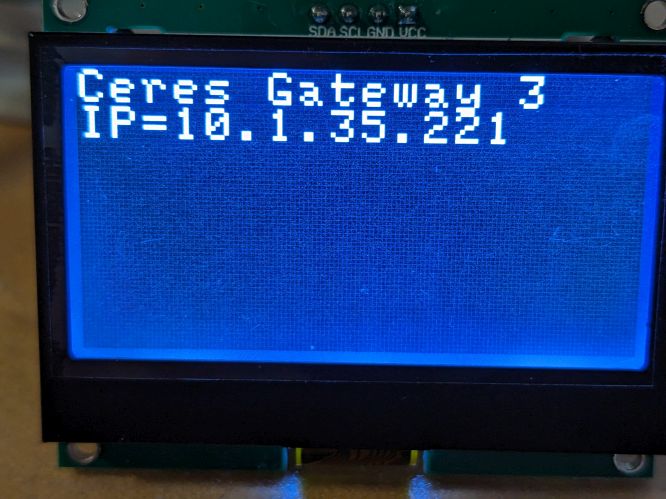
It’s almost perfect; the display works great and the ST7567S is both well supported with libraries if you don’t want to roll your own (e.g. U8G2 and U8G8 or this one derived from here) and provides a great deal of flexibility. The only problem is that the LED backlight (side light) is hard-wired to power (you can’t turn it off) which is fine for AC-mains powered applications, but a real bummer for battery-powered devices (where LCD displays are normally so attractive).
GM12864-59N LCD display with backlight
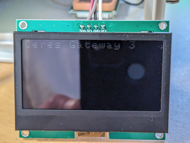
I tried disconnecting the backlight (remove the 100R current limiting resistor R5), but the LCD contrast is then so poor that it is unusable. It’s actually much worse than the picture below suggests which benefited from the optimal camera angle and the more sensitive camera sensor; for mere humans, the display is completely unusable without the LED backlight.
GM12864-59N without backlight
So this display might make it into my next AC-powered design, but for battery powered devices, I need something that lets me control the backlight.
I do a lot of IoT development involving battery-powered wireless devices. These devices must have very low average power consumption to facilitate long battery life. They typically spend most of their time in a low-power sleep mode, drawing a few uA or even nA and then wake periodically to take measurements, operate controls, and transmit and receive messages. Transmitting can draw hundreds of mA.
So the dynamic range of current draw can span 5 orders of magnitude! Moreover active periods are often very brief (sometimes just tens of uS). Measuring that sort of highly dynamic power consumption with fast transient events is a big challenge.
Current is generally measured by measuring the voltage drop across a shunt resistor. Unfortunately, a shunt resistor large enough to allow measuring a few uA will introduce unacceptable voltage drop if trying to pass 500mA. So measurement devices must have many shunts and measurement circuits and be able to switch them in/out of line very rapidly while sampling the voltage drops across the shunts very fast.
My go-to device for this sort of dynamic power analysis is the Joulescope which is simply phenomenal. It has 1.5nA-1mA resolution (depending on the measurement range), samples at 2MS/s (250kHz BW) and switches shunts as fast as 1us. The software is excellent too. The only problem is: it’s expensive (around $1K), so it’s not something I can put on every bench or easily design into test fixtures.
Hence my latest tool: the Nordic Power Profiler Kit II (PPK2) which is sort of a poor-man’s Joulescope. It has many of the Joulescope’s features, but all are spec’d significantly worse. It’s also 1/10 the price. It also has one feature that the Joulescope lacks and is quite useful. The PPK2 is a credit-card sized device, powered by one or two micro-USB cables (depends on how much current you need…in my case, one is usually enough). It samples much slower (100Ks/s max) and is limited to 5V; resolution varies from 100nA to 1mA depending on the shunt range, it doesn’t measure voltage at all (so you can’t use it to observe voltage drop), and the software is significantly less mature. It looks like a bare board, but the components are actually covered/protected by a clear acrylic shield so it’s bench/desk safe.
On the plus side it has a built in programmable power supply that can output 0v8 to 5v0 (drawn from the USB supply). That by itself is an incredibly handy feature. With the Joulescope, I need it and a bench power supply to power the DUT. The ability to power a 3v5 DUT *and* monitor its dynamic power behavior while only tying up one USB port and the bench space needed for a credit-card-sized device is super-cool. It also has 8 digital inputs you can use as a poor-man’s logic analyzer to correlate digital events (e.g. turn on transmitter) with power consumption. The Joulescope has such inputs too.
So far, I like it. The measurements match my Joulescope nicely – except for very fast transient events where the Joulescope shines and the PPK2 suffers. The built-in programmable supply is awesome. The software needs some work. Most critically, the data logger needs a continuous mode where it fills the RAM buffer and then wraps; the software currently fills the buffer and then stops, requiring a manual restart to keep monitoring current consumption and resetting all counters. This is particularly bad when what you want to do is measure average power consumption over a long period (e.g. a day or a week). At 100Ks/s, the RAM buffer fills very quickly so you can’t monitor the DUT at high speed for more than 500s. At 1Ks/s you can monitor for 13h, but fast events will be missed or improperly measured which defeats the purpose of such devices. What’s needed is a continuous mode that wraps when the RAM buffer is full but keeps accumulating average, max, and total power used. (Nordic are you listening?)
Overall, I’m pleased with the PPK2 so far and expect to buy more for use on benches and in test fixtures. If you can’t afford a Joulescope (or just want a super-compact USB-powered variable supply), the PPK2 seems like a great choice.
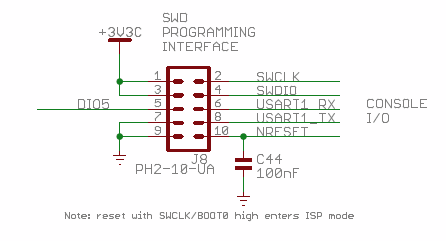
There are three things every STM32 developer wants from a debug dongle:
Power (3v3, 1v8)
SWD
UART
So I was excited when ST released their next gen debug interfaces (STLinkV3) and had included support for 1v8 targets and a UART. Was third time a charm? Unfortunately, not. Although the UART and support for lower-voltage targets is a welcome addition, ST made three unfortunate moves with the MINIE that are hard to fathom:
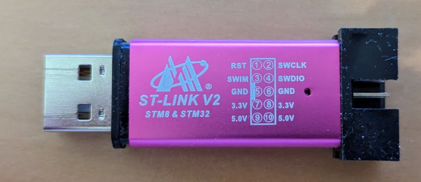
Most notable was their attempt to force use of the STDC14 connector by *only* providing a 0.050 pin header for connections to the target via a fairly fragile connector. It would have been *much* better for it to have a shrouded 2×5 0.100″ pin header (like the “aluminum shell” STLinkV2 clones show below). These would allow use with the ubiquitous Dupont jumper wires that litter every developer’s desk. A tiny PCB with an SMT 2×5 female 0.100 on one side and STDC14 male on the other could have easily adapted to STDC14 when desired, but it’s much harder to go the other direction.
It can’t power the target. Even the sub $3 STLinkV2 clones can power targets at 3v3 and 5v. This is incredibly useful, adds virtually no cost (5V is available from the USB i/f and there’s already a regulator on the STLink for its own uC). An STLink that has SWD, UART, and Power is exactly what every STM32 developer wants…now you need the MINIE and an external power supply!
Finally, there’s the USB-C female connector. Even new laptops have very few USB-C ports (but many USB-A ports); the desktop situation is even worse. The interface itself is only USB 2.0 and the board and can’t supply power to the target, so I can see no rational reason for this choice. I suspect some PLM who has never done any development decided this would be “forward looking”.
The sub-$3 “aluminum shell” STLinkV2 clones nail the mechanical design. They can also power 3v3 and 5V targets. It’s only missing a UART and 1v8 support to be perfect.
So what to do?
You can keep using STLInkV2s, but as designs increasingly move to 1v8, that becomes a problem, requiring a high-speed voltage converter…The STLinkV2 runs an STM32F103 which only runs to 2v0 so you can’t just replace the regulator…and the STLink V2 lacks a UART.
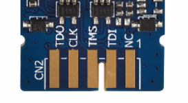
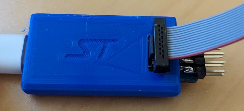
There are adapter boards to convert STLink V3 STC-14 connector to 0.100 pin headers; I covered these in an earlier post discussing the STLink V3-PWR (which does supply power and is a single device solution for most STM32 development/debugging). However, the adapter boards just add another set of wires to clutter your bench and come loose at inopportune times. Fortunately, ST provided an edge connector on the V3MINIE for an imagined board-to-board configuration, and although they spaced the pads at 2mm, you can make them work for a 2.54mm pin header.
The JTAG/SWD pins map to SWD as:
TMS = SWDIO
CLK= SWCLK
TDO = SWO (which I rarely use)
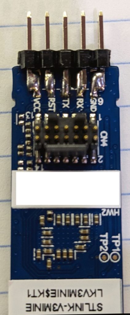
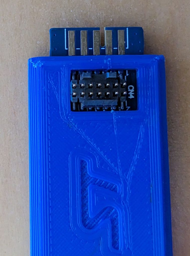
It’s easy to solder a 2×5 0.100″ (2.54mm) pin header onto the 2mm pads; just center the middle pin on the middle pad and the other pins are close enough that you can easily make it work.
The soldering here is sloppy, but it shows the concept. The 2×5 pin-header is rock solid when mounted and provides access to all of the pins I use. The UART-side pins (shown to the left) are obvious.
Next time I’ll use a shrouded connector, to prevent accidental contacts and also to have a place to put a small label for each pin (you can’t see the silkscreen for the edge connector contacts when the board is in the 3D-printed enclosure)
ST has also kindly placed an STL file for a 3D-printable case on the product page (under CAD Resources). If you’re using Cura to slice the model, you’ll also need to uncheck the “Union Overlapping Volumes” box in the Mesh Fixes section of the print settings or it will fill in the STDC14 opening. Otherwise, it’s a very nice, compact enclosure with an excellent snap-fit and it holds the PCBA securely.
The original version of the enclosure posted on ST’s product page had the opening for the STDC14 connector slightly shifted and so you had to cut it a bit to make room for the connector. Within a day or so of reporting this to ST (8/2/2023) they had fixed the issue and sent a new STL file to test and it fit perfectly. I expect it will replace the original version shortly.
Go ST!
Next up:
Figure out how to get the SWD functionality working from the 0.100 header pins
Find a solution for powering the target. If you know of any, please let me know!
ST: if you’re listening, PLEASE give us a nice compact dongle like the V3MINIE but with a USB-A connector, pads for 0.100 pin headers, and 3v3 and 1v8 power outputs.
Update 5/1/2025
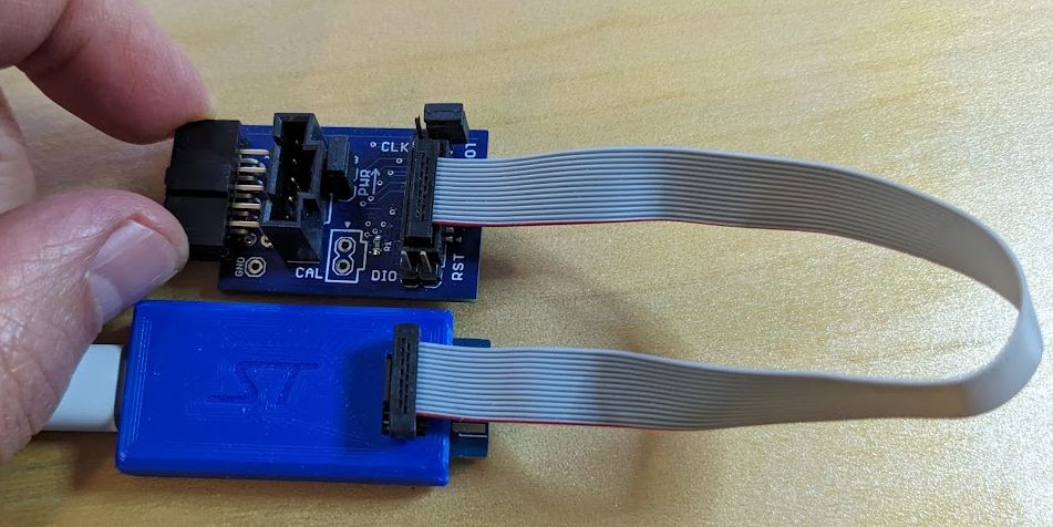
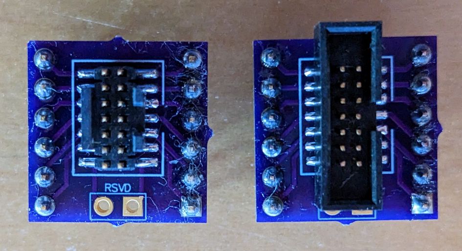
Because both the 0.050″ STDC14 connector and 0.100″ flying leads are a pain, I spun a quick 2-layer adapter PCB with a 0.050″ connector (CNC Tech 3221-14-0100-00) that connects via ribbon cable to the MINIE and a more robust 5×2 pin 0.100″ connector (Sullins SFH11-PBPC-D05-RA-BK) that plugs directly to my STM32 target. The SWD connections (DIO and CLK) can be disconnected via jumper so the UART alone can be used.
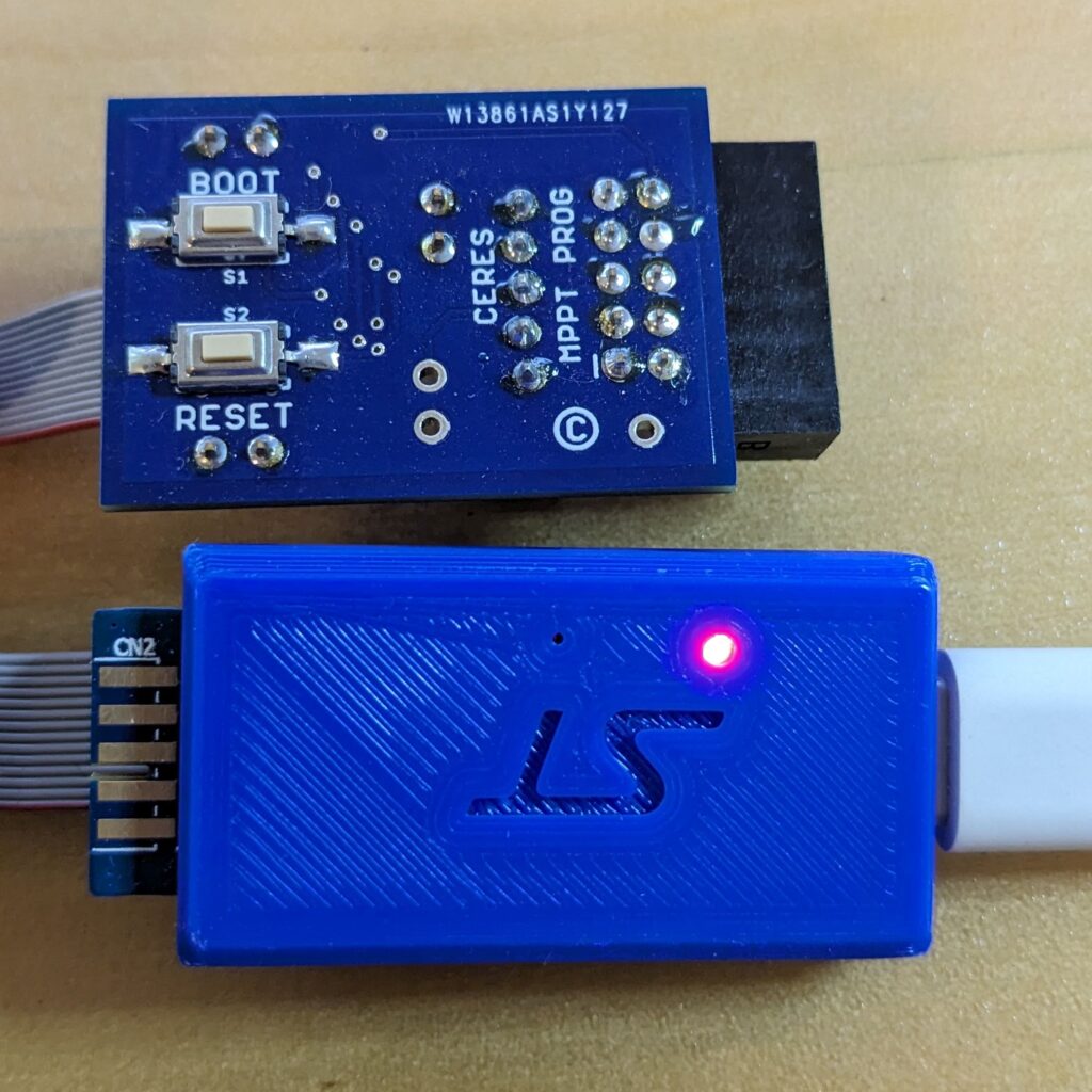
On the bottom of the board, tactile switches make it easy to manually reset the target and/or to put it in the DFU bootloader mode.
The target connector is a super-cheap 2×5 keyed 0.100″, shrouded pin header that brings out all of the signals needed for factory programming and calibration as well as development and debugging.
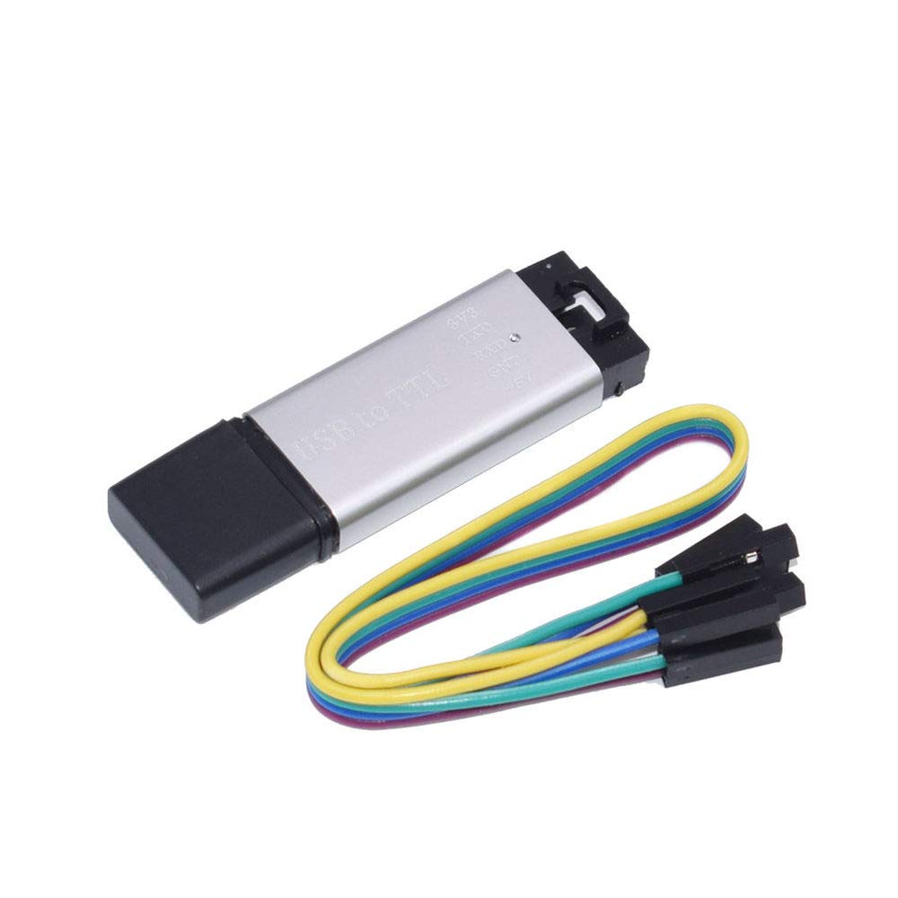
Aluminum Shell serial dongle
The adapter board also has a 1×5 locking header (Molex 0705430004) to support a straight-through, locking cable (Molex 216270-1053) to allow use with the ubiquitous low-cost “aluminum shell” USB-to-TTL UART dongles. Those can then be used in place of the MINIE if only serial comms with the target are needed. These adapters can supply power as well which is often handy during development or debugging. When used with these dongles, the adapter includes a jumper to disconnect power or to allow measuring target power consumption.
Update 2023-July: I no longer recommend using this until ST software support improves. At present, there are simply too many issues and it is a frustrating experience. The software seems somewhere between alpha and beta quality: the software that does work has major issues and many important software applications (including from ST) don’t work with it at all (including openocd which works fine with other STLink V3s).
I do a lot of design and development work using STM32 microcontrollers. The low-cost STLinkV2 hardware debug tool is part of what has made these processors so successful: the ability to quickly, inexpensively, and easily flash and debug firmware is a big deal. ST has gone a long way to make life easy for developers and we love them for it!
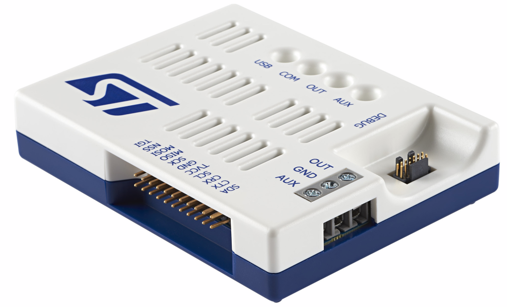
I have boxes of STLink V2s and clones; I use them all the time. Recently, I’ve started migrating to the STLink V3 and this post covers their most expensive variant: the STLINK V3-PWR which integrates some interesting features including:
SWD debug tool (flashing, debugging target)
USB-to-serial converter
variable power source for target (1v6 to 3v6 in 100mV steps)
dynamic current monitoring (100nA to 500mA) with 100ksps (50kHz BW)
It has additional hardware capabilities (SPI, I2C, GPIO, JTAG) that I haven’t tried yet (and it’s not clear that software support for them is ready).
Key Strengths
The STLink v3 is fast for flash/debug – even faster than the V2 (which was plenty fast)
The integrated serial interface works perfectly and saves another plug
Nice injection molded enclosure
The variable power source lets me test devices at voltages other than 3v3 and 5v which is more useful than it sounds…it’s often important to understand how the DUT will operate at 1v8.
The ability to monitor dynamic power consumption during development is incredibly useful. I didn’t fully understand this until I started using a Joulescope and realized how much added visibility it provided. I now routinely develop with the DUT powered through a Joulescope so I can better “see” what’s happening. The V3-PWR dynamically switches between 4 current ranges to provide a huge dynamic measurement range without imposing excessive burden voltage.
Cost:
$95 is crazy expensive for an STLink and serial dongle (V2 clones and serial dongles are individually available for as little as $2 from AliExpress in nice compact aluminum shells).
$95 is crazy cheap for a dynamic power monitor that covers a wide enough current range for IoT development is hard to come by for even a fraction of the price. The Joulescope, is roughly 10x the price (but much more powerful).
If ST make the design public as they did with the V2, we can expect to see the price decline dramatically once Chinese clones appear.
Hardware Limitations:
100ksps (50kHz claimed BW) sounds great, but in reality, that sample rate doesn’t provide enough resolution to understand the dynamic power consumption of many IoT devices. It’s super-common for battery-powered devices to wake briefly (uSeconds), do something, and go back to sleep. This is one of the major differences with the Joulescope (2Msps, 300kHz BW).
No pass-through current/power monitoring. Batteries have higher impedance than most line-powered supplies and that impedance varies with temperature and other dynamic feactors (e.g. passivation). The V3-PWR lets you observe the consumption of the DUT, but not its dynamic interaction with a battery. (another difference with the Joulescope).
Power to the DUT is via ~3.5mm screw terminals…not banana jacks, not pluggable screw terminals, not even lever terminals…this was the wrong place to save a few cents.
Connection to the computer *requires* USB-C or the rare USB-A port that supports both data and charging. Maybe this isn’t a big deal or even a limitation, but it’s worth being aware of.
That Dang STC14 connector
The biggest DOH! with the entire STLinkV3 series is ST’s adoption of a 50-mil “STDC14″ connector. 0.050” (1.27mm) connectors are simply awful, particularly for developers. Many targets won’t have the same STDC14 connector and now you can’t use the ubiquitous 100-mil dupont jumpers as we did with STLinkV2. Instead, you need a breakout board to adapt the 0.050 pins to 0.100. You can get inexpensive STDC14 breakout boards from OSHPark (9 PCBs for $11.10 shipped) and mount either these nice but very expensive and somewhat fragile Samtec connectors (left) or these much cheaper and more rugged CNC Tech connectors (right).
No cumulative or average power measurement. This is a huge deal for battery-powered devices (and one that ST can and should add to their software). Understanding average power consumption is key for most battery-powered IoT devices. The sampling limitation might limit accuracy, but this is an easy-to-implement and important missing feature.
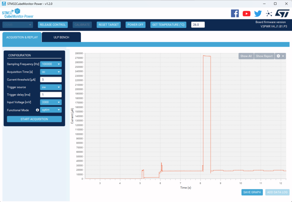
The UI is limited (something ST will also hopefully improve over time). It provides a graphical display of current measurement (see below), but is missing features we’ve come to expect from scope-type equipment such as: horizontal or vertical cursors to make and document precise measurements, automatic axis scaling, adjusting the time-base dynamically, etc. ST software developers would be smart to license Joulescope software for the V3-PWR.
When the software associated with the V3-PWR matures, it will get a thumbs up from me. If/when cheaper clones start appearing, I’ll probably have a box of these to replace my STLink V2s. If ST provides an API, these could also form a very useful building block in many factory test fixtures.
Competitors
Nordic Power Profiler Kit 2 (PPK2) – similar price, wider voltage/current ranges, can measure external current sources (i.e. battery), but no debug/serial functions and no enclosure.
NXP MCU Link Pro – half the cost, but you must select one of two current measurement ranges using a jumper and neither of those ranges fully cover my measurement needs. Within the selected range, the MCULink dynamically switches between 2 sub-ranges, allowing good dynamic range, but not on the level of the other devices. It also has more limited power supply capabilities (two fixed voltages: 1v8, 3v3) and has no enclosure.
Disk Abuse
I left the monitor running overnight at a high sample rate with acquisition time set to infinite. It turns out that this writes a ton of data to the disk and by morning it had chewed through 160GB of disk space! Even worse, it’s not obvious where the disk space went! So for other users who find this issue, the power acquisition log files are in Users/myUserName/AppData/Local/Temp/Power_Monitor/Acquisition.
ST could significantly improve the software application (STM32CubeMonitor-Power) by adding a few features, some of which seem quite easy:
Checkbox to En/Disable logging (off by default) so you can watch power consumption as you develop/test.
Link to the acquisition logs folder so users can find it easily
Stop/play button so you can pause acquisition to measure an event and then resume
Cumulative power usage counter (so you can confirm expected average power consumption over a long test)
Cursors (current and time) so you can measure and document events
Auto-scale of the Y-axis should adjust to mA when appropriate. A scale from 0..500000uA is just silly and it’s surprisingly annoying to try to distinguish 15000 from 150000.
We all know things are ugly out there, but things are particularly ugly in the growing world of connected devices where security is often an afterthought or under-powered for the modern internet.
I was reminded of this yesterday when I needed to recover the root password for an internet device (with the permission of the device’s owner who had forgotten it…so it was legit to hack). Like many such devices, it used a scaled-down older linux kernel, BusyBox, and an old-fashioned /etc/passwd file where salted passwords are stored md5-crypt hashed. (format: $1$<salt>$<128-bithash>.
Fortunately (but also worrying), a popular hacking tool (John the Ripper) makes short easy work of such files. And when I say “easy”, I mean ridiculously easy and when I say “short”, I mean weak passwords are cracked in seconds. If you have access to the passwd file (let’s call it passwd.txt) you would just run the command “john passwd.txt” and in a few minutes, voila: out pop the decrypted passwords. You can enhance JtR with (big) lists of common passwords; there are free lists here and you can also buy lists. You can run JtR on a multi-core machine with a word list using a command like:
john –fork=8 –wordlist=mywordlist.txt filetocrack.txt
In the past, I wouldn’t make a post like this for fear of encouraging hacking, but these days, that fear is misplaced. Tools like JtR (and many much more powerful) are so easy to use and so widely available that *any* hacker at any level knows about them. So rather than keeping head in sand, it’s time to bite the bullet and start assessing (and fixing) your products’ security.
Hire someone to help with security if:
your system stores plaintext passwords
your passwords aren’t salted before hashing
you don’t have a delay before re-entering the password after a few failed attempts
If your products run on small/old linux kernels and/or otherwise use md5crypt for password hashing, consider upgrading and hash passwords using at least SHA256.
Prompt users when they are entering new passwords for what makes a quality password: use an obscure phrase rather than single words or a word with some numbers or some variation on their username.
Store usernames and passwords separately such that only the root user has access to the password file (/etc/passwd and /etc/shadow)
Check new passwords against known lists of pwnd passwords and warn the user.
Run tools like JtR against your own passwd stores and if it quickly guesses your passwords, know that hackers will be doing the same thing.
If possible, don’t use passwords at all on internet-facing systems; use public key certificates instead.
In your own (home/business) networks, segregate insecure devices (i.e. nearly every internet-enabled appliance: cameras, TV streamers, doorbells, etc.) from your computers and storage systems. Devices belong on the guest network or separate VLANs…not on your main WiFi/LAN.
Don’t use the same passwords in internet appliances that you use for things you care about. Assume the internet devices have been cracked. The security in internet appliances is usually *vastly* worse and when hackers crack that doorbell/camera, you don’t want that giving them access to the rest of your network, bank account, etc.
Ideally, use a different, good password for every account. Use a free tool like PasswordSafe to keep your passwords secure; encrypt the safe where your passwords are stored with a single very good password that you don’t use anywhere else and then you can store it on the cloud (OneDrive, GoogleDrive, whatever) so you have easy access to your passwords, but hackers don’t.
When folks need a small embedded linux machine for control applications, a Raspberry Pi is usually the first thought. I’ve made good use of Raspberry Pi Zeros and 3Bs but have been reluctant to adopt the RPi 4 due to the apparent need for active cooling, high power consumption, very poor availability, and high pricing (it makes little sense to use an RPi when you could use a much more powerful x86-family platform).
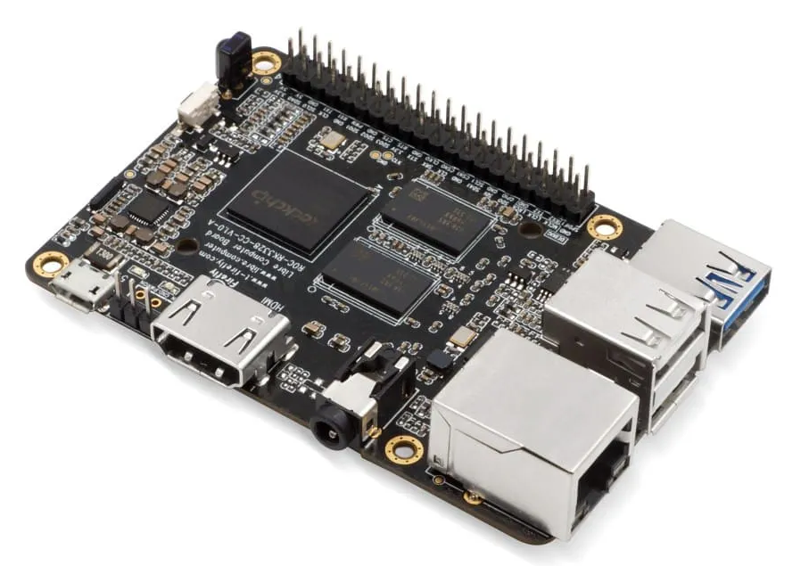
With RPis out of stock for months and being scalped everywhere, I decided to try a Libre Computer ROC-RK3328-CC which is footprint/form factor compatible with the Raspberry Pi and can run Ubuntu, Raspberry Pi OS, Armbian, Debian, Android, and many other OS. The docs are here. The board comes in two versions: 2GB for $45 and 4GB for $55 – those prices are with free one-day shipping via amazon prime and they are available immediately. I bought the 4GB version which is 4x the memory of an RPi 3B+; the memory is also DDR4 vs. the DDR3 used on the Pi. The board is easily passively cooled; I bought the custom heat sink ($10) although any similarly sized heatsink should work fine.
I tried Ubuntu desktop but was disappointed by the bloat and installed Raspberry Pi OS (a Debian derivative) instead and am very happy with it; I installed the desktop (not lite) version. The board is DIN-rail mounted using this high-quality mounting solution. It runs several minicom sessions monitoring/logging other embedded boards as well as a Postgres database and Java backend data collection application. Even over TightVNC, it feels snappy and doesn’t break a sweat (stays between 45 and 47C); it is using less than 1/4 of the available RAM (but would have used nearly all of the RAM on an RPi3).
Other upsides: 4K video (mainly of value for HTPC applications) and USB 3.0 – much more important because it makes it worthwhile to connect an external SSD which will be much faster and more reliable than uSD storage. The main downsides relative to the Raspberry Pi are: no WiFi/Bluetooth and no Pi-compatible camera connector. I didn’t need those for my application (which is rack-mounted and connected to Ethernet), but if you need either, you can easily solve them via USB connection.
For storage, I use Sandisk Extreme uSD cards. 64GB costs $11 and is plenty of storage for my application (I’m only using 6%); if I need more, storage or speed, I’ll use an external M.2 card connected via USB 3.0. Note: there is a huge difference in performance and reliability between SD storage cards used in RPi applications; some cards won’t work at all, some will work but at half the speed of others (see this performance comparison). I’ve tried a bunch and settled on the Sandisk Extreme which offer good speed with a cost only slightly higher than lesser cards; the benchmarks bear this out. If I were doing something more disk-intensive, I’d consider either a board with a native M.2 interface (like the Odroid M1) or an x86 board with a native SATA or M.2 interface.
Note: uSD cards aren’t meant for frequent writing (as in linux logs), so if you want your card to last, I strongly recommend using a utility like log2ram that creates a small RAM disk for the /var/log partition (you can add others) and then periodically flushes that partition to SD storage. This will dramatically lengthen the life of your SD card; see here for more info.