
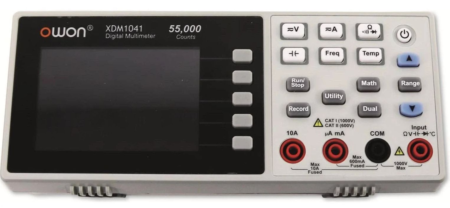
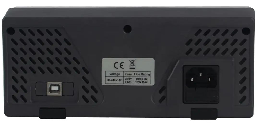
I have generally had good experiences with Owon’s USB oscilloscopes and decided to try their low-cost bench DMM, the XDM1041. It is a 4.5 digit, 55K count DMM, so it’s not going to displace anyone’s 6.5 digit Keysight or Keithley, but it is cheap (under $100 on AliExpress), small, AC-powered, has a lovely display, and perhaps most importantly has a USB SCPI interface so you can use it for test automation (note: you cannot power the DMM via the USB port). The version I have is AC-powered, but it’s also available with a battery option (XDM1241) for portability; otherwise, the two models are spec’d the same. There are lots of comprehensive reviews; a particularly good one is here: https://www.youtube.com/watch?v=xzsmyjWFtW8 (defpom); here’s a teardown. I’ll try not to reproduce what’s there but rather will focus on adding details or exploring features rarely covered.
Frequency Counter
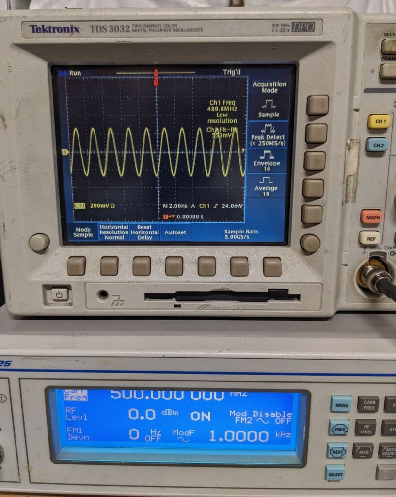
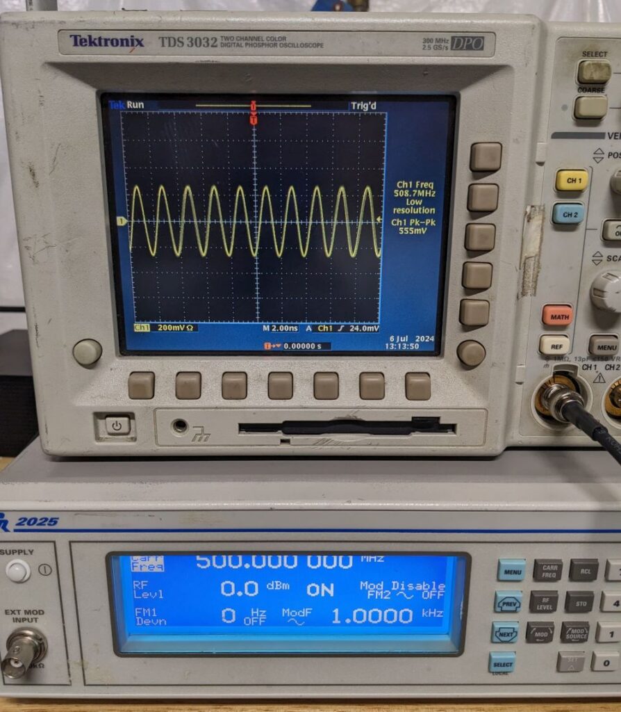
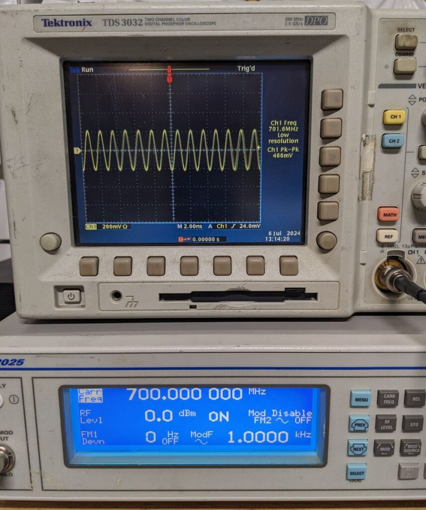
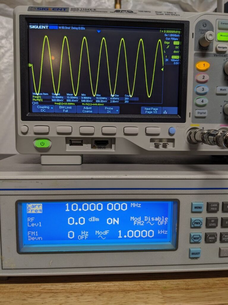
I wanted to test the frequency counter myself because most reviews don’t provide enough analysis of the voltage required for the counter to operate at any particular frequency:
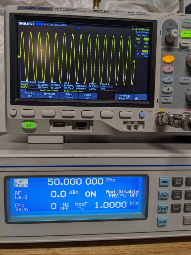
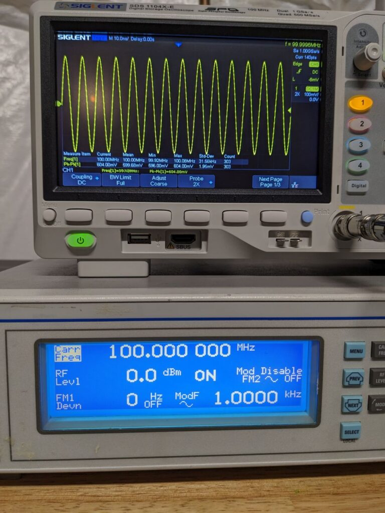
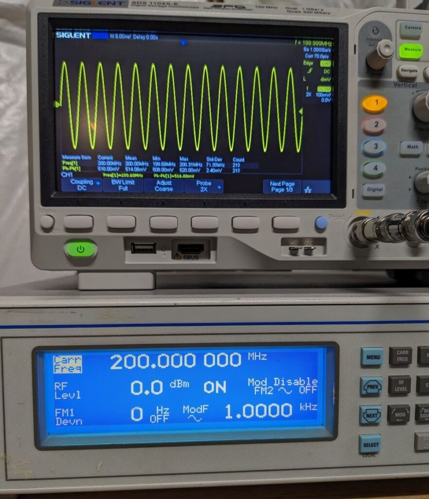
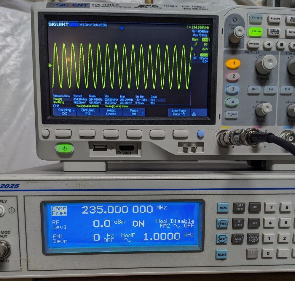
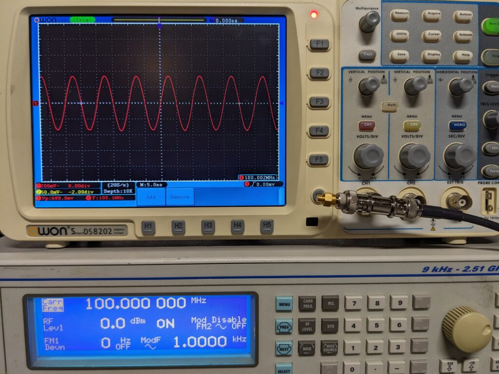
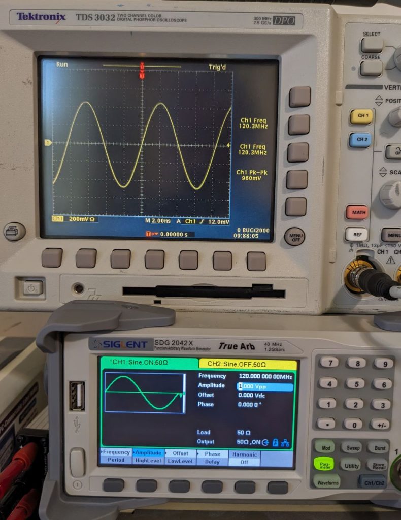
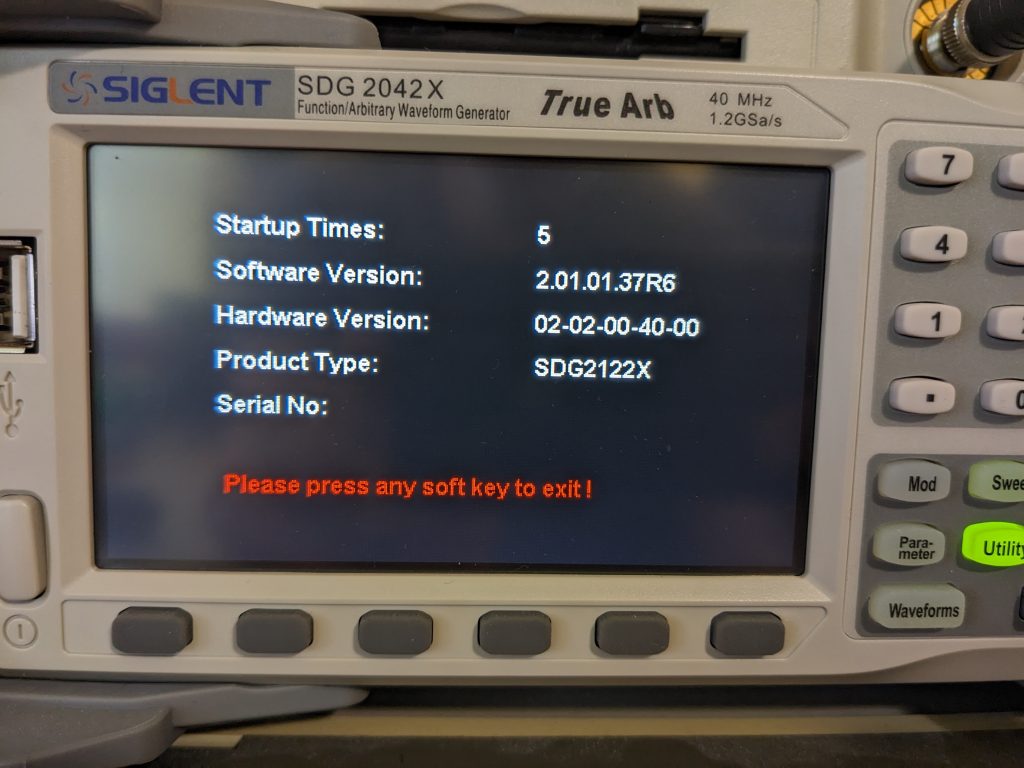
The counter as advertised as working up to 60MHz. Obviously the 4.5 digits creates an inherent limit to the resolution, but it’s accuracy is advertised as 0.2% + 10 counts. I tested using a 120MHz SDG-2122X AWG slaved to a DOCXO (very stable/accurate) external frequency standard. The AWG was generating a sine wave and was connected to the DMM via a 1m RG59 cable and a BNC-to-banana adapter on the DMM (I think this is the same adapter used in the defpom video). I’ve documented the readings and the minimum voltage required for a stable reading below:
View frequency accuracy vs. required voltage table
| AWG | DMM Counter | Min Vpp |
| 55kHz | 54.998kHz | 1.5 |
| 100kHz | 99.997kHz | 2.0 |
| 550kHz | 549.98kHz | 2.0 |
| 1MHz | 999.97kHz | 2.0 |
| 5.5MHz | 5.4998MHz | 2.5 |
| 10MHz | 9.9997MHz | 2.5 |
| 16MHz | 15.999MHz | 3.3 |
| 25MHz | 24.999MHz | 3.3 |
| 30MHz | 29.999MHz | 3.3 |
| 40MHz | 39.999MHz | 3.3 |
| 55MHz | 54.998MHz | 3.6 |
| 60MHz | 59.998MHz | 3.6 |
The DMM requires a fairly strong signal; even low frequency signals required at least 1.5 Vpp. That said, and much to Owon’s credit, the frequency accuracy is well within spec and fairly good for a devices whose timebase is just an XO. Consider the 1MHz reading: 0.2% is 2kHz and the actual reading (999.97kHz) was within 30Hz so the frequency performance dramatically exceeds the spec.
The primary limitations appear to be the requirement for a strong signal and the counter resolution of 4.5 digits. If testing a 16MHz crystal oscillator, 4.5 digits limits each count to 1kHz or 62.5ppm. This might be good enough for confirmation of oscillator operation, but is insufficient to confirm operation within the specs of a +/-20ppm or even a +/-50ppm crystal.
SCPI and DC current measurement
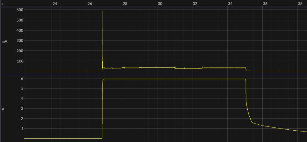
I tested the SCPI interface which uses the USB connection to a Windows 11 computer. The port enumerated as a serial interface (CH340) and uses 115kbps 8/N/1. I tested using TeraTerm as the serial interface program. I wanted to see if I could use the DMM to provide accurate current measurements for some test automation (short answer: yes, it works great)
- *IDN? (returns “OWON,XDM1041,2212364,V3.3.0,3”)
- CONF:CURR:DC [500E-3 | 500E-6] -3=500mA, -4=50mA, -5=5mA, -6=500uA
- FUNC? (returns “CURR” (with quotes))
- RANGE? (returns range e.g. “500 uA”
- AUTO? (returns “1” if in auto-scaling mode, “0” for manual)
- MEAS? (returns current in scientific notation: “1.557310E-05”)

