Updated 8/2019: My daughter inherited the Acer CB3 and makes extensive use of it; I no longer have the Toshiba; it is still a great machine, but my over-50 eyes now need larger fonts than are rendered on a 13.3″ FHD screen.
—————————————–
I’m not a big fan of expensive laptops. Computer equipment depreciates at a terrific rate and portable computers are subject to loss, theft, and damage so I want the least expensive machine that will do the job. That said, I also want it to be compact, light, fast, and last all day on a charge (i.e. an ultrabook). This may seem like a tall order, but I have found three solutions that I’m happy with. All involve hacks:

Toshiba Chromebook 2
For MS Windows: The Toshiba Chromebook 2 Model CB35-C3350 has a Core i3-5015U with 4GB DDR3 and a 13.3″ 1920×1080 IPS display. It’s meant as a Chromebook, but you can replace the internal SSD with a larger one (necessary for it to be useful and I had a spare 64GB M.2 drive on hand) and thanks to coolstar.org, you can install Windows, turning it into an excellent Windows ultrabook. The main downsides are limited battery life (4-6 hours) and as I’ve gotten older, I find that 13.3″ screen is a little too small. However, it is extremely portable, fast, sleek, and can regularly be found on eBay for $250-300.

Acer Cloudbook 14
Ultra-cheap-book: Ubuntu Linux: The Acer One Cloudbook 14 has only 2GB of RAM, a slow 1.6GHz Celeron N3050 processor, 14″ 1366×768 display, 64GB SSD, and 10 (real) hour battery life. So other than the battery life, this is low-spec. It’s woefully under-powered for running Windows and slows to a crawl as soon as you start doing anything with it. Fortunately, it is better spec’d for Linux and once I loaded Ubuntu, it was surprisingly snappy and effective. My old eyes appreciate the larger screen and the very long battery life makes it a great knock-around machine. You can’t use it for for much software development: the big IDEs like NetBeans and Eclipse are too much for it, but most other apps run just fine. It can often be found on eBay for $50-$100 and it’s tough to beat that for a thin, light, all-day laptop that’s practically disposable.
Gallium (Ubuntu) Linux: Last but not least is the Acer CB3-431 which is a 14″ Chromebook with a full HD screen (1920×1080), 4GB of RAM, 32GB eMMC storage and a quad-core Celeron N3160 1.6GHz processor; the case is aluminum and looks pretty snappy – an apple knockoff. This is my current carry machine.
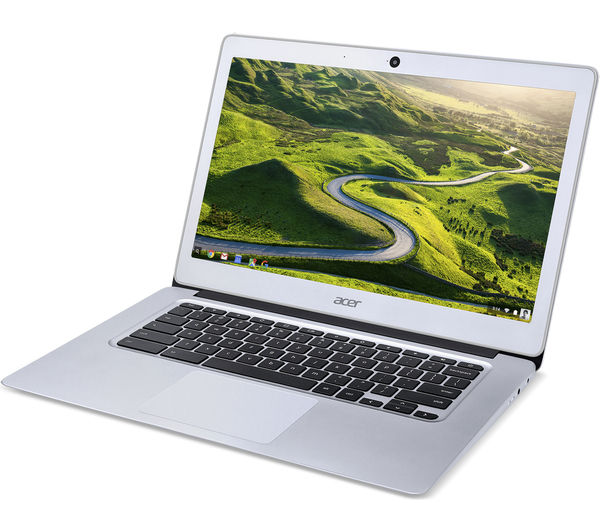
Acer Chromebook 14
You can follow these instructions which use Mr. Chromebox to replace the BIOS and install Gallium OS (a great Ubuntu variant designed for Chromebooks) and turn it into a real linux laptop while keeping ChromeOS as a bootable option. Because linux is relatively lightweight, even with LibreOffice, Slack, Thunderbird, Wine, EmBitz, Eagle, Oracle Java, NetBeans, Tomcat, Arduino, and a full gnu cortex cross development environment installed, I still have used only 50% of the Gallium root partition and it runs fast. Battery life appears to be > 8 hrs. Dual-boot has come in handy (it let me recover when a grub update prevented linux from booting) so I recommend it as well as setting the GBB flags as described in the instructions.
Note: if you update grub, it will ask you which partition to use: select the one that covers the entire disk (mmcblk0 I think), not just linux partition (mmcblk0p7). If you select the wrong one (or both), it will not boot linux. If you’ve dual-booted, you can reboot to chromeOS (ctrl D at startup screen) and recover.
If you are OK with (or prefer) linux on a light, inexpensive laptop, the Acer CB3-431 is a nice choice and is now the laptop I regularly carry. It is commonly available “recertified” from vendors like NewEgg for $180 making it not quite disposable, but still very inexpensive. The main downsides are the non-expandable storage (32GB) and the lightweight processor, however I’ve found it extremely usable, all of my apps fit nicely and run at acceptable speeds. Unfortunately, 1920×1080 is proving tough on my over-50 eyes, even on a 14″ screen.
So I’ve ended up with a Chromebook running Linux, another running Windows, and a Cloudbook running Linux…none of them running what they were intended for…weird!
What I’m still looking for is a thin laptop, less-than 4lb, 15.6″ screen with full HD, Core i5 processor, 8GB of RAM, 128GB+ of SSD, and 8hr+ battery life…for around $300. Suggestions are welcome!

 ike it.
 eco-system: the main down-sides are that it uses proprietary software and